


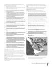
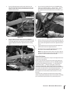
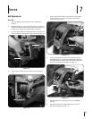


Push the belt forward then down until it is looped over the
lower pulley. See Fig. 7-2. Do not yet seat it in either of the
lower pulley’s grooves.
NOTE: A blunt object, like a ruler, can help you push the
belt downward if needed.
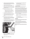
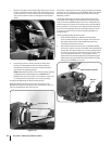
Move the top half of the belt up and over the rubber
reverse disc, but do not seat it in either of the grooves in
the top pulley.
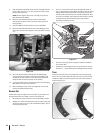
Place the Wheels/Tines/PTO Drive Lever in NEUTRAL.
Move the top half of the belt into the HIGH Range groove,
the groove closest to the engine, on the top pulley. See Fig.
7-5.
Move the bottom half of the belt into the HIGH Range
groove of the lower pulley. If extra slack is needed, hold
up Wheels/Tines/PTO Drive Lever while moving the belt.
Verify the belt is seated properly on the pulleys.
To move the belt to the Low Range position. See Changing
Belt Speed in the Operation Section.
After installing the belt, check and adjust for correct belt
tension as explained previously.
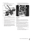
Reverse Disc
Follow these steps to replace the reverse disc. If your tiller has a
Bumper Attachment mounted, it must be removed first.
Move Wheels/Tines/PTO Drive Lever in NEUTRAL position.
Wedge a ⁄”-thick board between top of engine pulley and
cast iron housing next to it. This immobilizes pulley. Avoid
contacting reverse disc.
9.
10.
11.
12.
13.
14.
15.
1.
2.
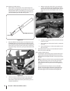
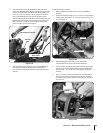
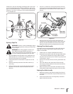
Use a ⁄” wrench to loosen the mounting bolt shown in
Fig. 7-6. Remember to immobilize the pulley with the wood
wedge while loosening the bolt. If necessary, pry the disc
from the pulley with the tip of a screwdriver. Back the bolt
out as far as possible. Then angle the disc a little to remove
it. Bring the bolt and lockwasher along with the disc.
Installing a new Reverse Disc.
Do steps 1-through-3,in the opposite order to install the
new reverse disc.
Tighten the mounting bolt securely, and check for correct
operation — see the Maintenance & Adjustments section.
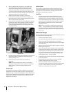
Tines
Inspect the tines for wear or damage after every 30 operating
hours. The rate of wear depends upon the hours of use and soil
conditions. With use, the tines get shorter, narrower and more
pointed. See Fig. 7-7.
3.
4.
5.
Drive
Belt
Figure 7-5
O
IL
Mounting Bolt
Reverse Disc
Wood Wedge
Figure 7-6
Worn New
Figure 7-7
38 sectiOn 7— service