


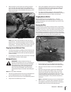
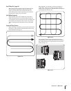
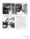
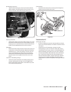

Then move the swing-out bolts out. See Fig. 4-21.
NOTE: Loosening swing-out bolts can be difficult. Use an
extra-long wrench for leverage.
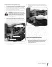
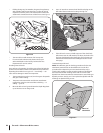
Tip the PTO power machine forward about one inch with
one hand while pulling the tine attachment back. Fig. 4-22.
8.
9.
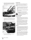
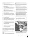
The guide pin on the power unit will slide out of the guide
hole in the tine attachment See Fig. 4-23.
Installing the Tine Attachment
Move the two PTO Power Unit swingout bolts outward and
slide the washers up against the bolt heads.
Remove the support block from under the engine and
slowly roll the power unit back next to the tine attachment.
Place the support block back under the engine.
Remove the dust cap (or protective wrapping) from the
dog clutch coupling on the tine attachment.
Carefully align the guide pin on the PTO Power Unit with
the alignment hole in the tine attachment and bring the
two units together. See Fig. 4-23.
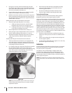
Move the two swing-bolts into the slots of the tine
attachment. Alternately tighten each bolt until they are
tight enough to make the concave washers flat. The bolts
must be very tight — if you have a torque wrench, tighten
each bolt to between 70 and 80 ft.-lbs.
NOTE: The swing-bolts must be kept very tight to prevent
damaging wear to the dog clutch coupling, alignment pin
or the alignment hole. Check the bolt tightness every 2-⁄
operating hours.
Remove the engine support before moving the tiller in a
forward direction.
10.
1.
2.
3.
4.
5.
6.
Swing-Out Bolt
Figure 4-21
Guide Pin
Mounting Hole
Figure 4-22
Mounting Hole
Guide Pin
Figure 4-23
23sectiOn 5 — OperatiOn