


CAUTION: Incorrect cable
adjustment couldcausethe
wheelsandtines to rotate
unexpectedly.Follow
adjustment procedures
carefully. Failureto do socould
result in personal injury or
property damage.
4. Checkfor correct spring/caNetension
as instructed in Section 5, Checkingand
Adjusting Forward Clutch Belt Tension.
5. Whentension iscorrect, tighten the two
jam nuts (B) securely.
STEP5: CHECKTRANSMISSIONGEAR
OILLEVEL
Thetransmission was filledwith gearoil at
the factory. However,besure to check the
oil level at this time to makecertain it is
correct.
IMPORTANT: Donot operatethe tiller if
the gearoil levelis low. Doingso will result
in severedamageto the transmission
components.
1. With the tiller on level ground, pull the
Depth Regulator Lever (R, Figure2-13)
backand then slide it to the second notch
from the top. NOTE:Ifthe lever does not
move, lift the tine hood flap and lookfor a
plastic tie securing the lever in place. Cut
and removethe tie.
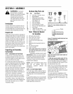
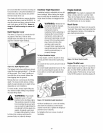
2. Removethe oil levelcheck plug (M, Fig-
ure 2-10) on the left-side of the transmis-
sion. (Due to dried paint on the plug
threads, it may require some force to re-
move the plug the first time.) Thegear oil
level iscorrect if oilstarts to flow out ofthe
holeas the plug is removed. If so, securely
reinstall the plug.
Figure 2-10: Gear oil level checkplug.
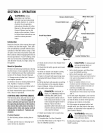
3. If oil does not flow from the checkhole,
add oil as follows:
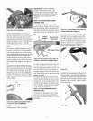
Figure2-11:Addinggearoil.
NOTE: Do not use automatic
transmission fluid or motor oil in the
transmission.
(a) Cleanareaaround the fill hole (N, Fig-
ure 2-11) and unscrewgear oil fill plug.
(b) If adding onlya few ounces of gear oil,
use APIrated GL-4or GL-5gearoil having
a viscosity of SAE140, SAE85W-140 or
SAE80W-90. If refilling an emptytrans-
mission, useonly GL-4gear oil having a
viscosity of SAE85W-140 or SAE140.
(c) Using aclean funnel, slowly add gear
oil until it flows from the gear oil level
check hole (N, Figure2-11).
(d) Reinstall and tighten securelythe gear
oil fill plug (M, Figure2-10).
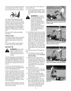
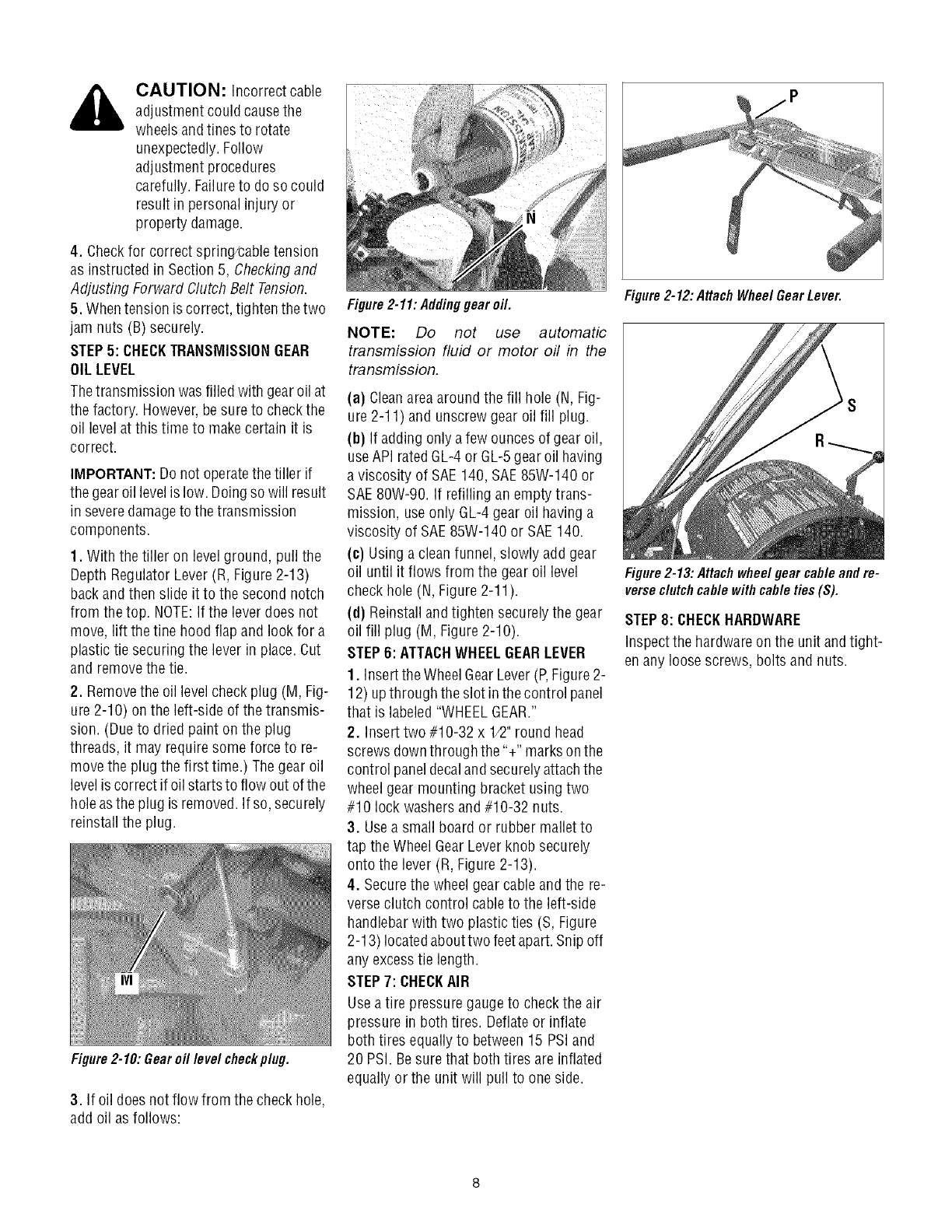
STEP6: ATTACHWHEELGEARLEVER
1. Insert the WheelGearLever (P,Figure 2-
12) upthrough theslot in thecontrol panel
that is labeled"WHEELGEAR."
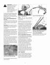
2. Insert two #10-32 x 1/2"round head
screws downthrough the'%" marks onthe
control paneldecalandsecurelyattachthe
wheel gear mounting bracket using two
#10 lock washersand #10-32 nuts.
3. Usea small board or rubber malletto
tap the Wheel GearLever knob securely
onto the lever (R, Figure2-13).
4. Securethe wheelgear cable and the re-
verseclutch control cableto the left-side
handlebarwith two plastic ties (S, Figure
2-13) locatedabout two feetapart.Snip off
any excesstie length.
STEP7: CHECKAIR
Usea tire pressuregauge to checkthe air
pressure in both tires. Deflateor inflate
both tires equally to between15 PSiand
20 PSI. Besure that both tires are inflated
equally or the unit will pull to one side.
Figure2-12: AttachWheel Gear Lever.
Figure2-13:Attachwheelgearcableandre-
verseclutchcablewithcableties(S).
STEP8: CHECKHARDWARE
Inspectthe hardware on the unit andtight-
en anyloose screws, bolts and nuts.