


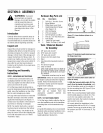
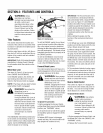

Figure2-4: Attachhandlebars.
5. Move the handlebarsup or down to
align thethreaded hole in the cross-brace
with one of thefour slots in the curved
height adjustment bracket.Placethe keyed
washer (E,Figure 2-3) on the flange head
height adjustment screw (F)with the
raised keys (edges)of the washer facing
down.
6. Threadthe height adjustment screw (F,
Figure 2-3) into the hole in the handlebar
cross-brace, making surethat the raised
keys on the washer fit into the slot on the
height adjustment bracket. Tightenthe
height adjustment screw securely. Next,
securely tighten the two screws and nuts
in the ends of the handlebar (M, Figure 2-
3).
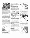
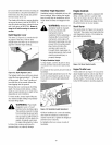
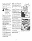
7. To removethe tiller from its shipping
platform, first carefully unwrap the wheel
gearcable (with attachedlever- seeFigure
2-5) from around the chassis. Movethe
Wheel GearLever (G) to the DISENGAGE
position--this allows the wheelsto rotate
freely. Usethe handlebarsto roll the tiller
off the platform.
Figure2-5:CarefullyunwrapWheelGearLe-
verandmovelevertoDISENGAGE.
IMPORTANT: Usethe DISENGAGE
position only when the engineis not
running. Before startingthe engine,the
WheelGear Levermust be placedin the
ENGAGEposition (seeSection3 for
details).
STEP3: ATTACHREVERSECLUTCH
CONTROLCABLE
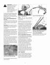
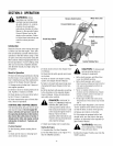
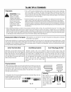
1. Carefully unwrap the reverseclutch
control cable (H, Figure2-6) from its ship-
ping position and route it upalong the in-
side edgeof the left sidehandlebar.A knob
and large hex nut (I) is installed on the ca-
ble.
Left Side ReverseClutch
Handlebar Control Knob
Slot inControlPanel
'1
Figure2-6:Attachreverseclutchcontrolas-
semblytodotted holeinhandlebarpanel.
2. Insert the cable into the slot in the con-
trol paneland fit the threaded assembly
into the holein theslot (seeFigure2-6). Be
sure that the flat sideof the threaded as-
sembly is aligned with the flat side of the
hole. Slide the hexnut (I) upthecable and
tighten it securely.
3. Testthe function of the reverseclutch
control cable by pulling the knob out and
releasing it. The knob should return to its
neutral position againstthe taperedbush-
ing. If it doesn't, contact your local dealer
or the factory for technical.
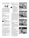
STEP4: ATTACHFORWARDCLUTCH
CONTROLCABLE
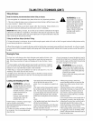
1. Removeany fasteners (rubber bands,
tape, etc.) that may securethe Forward
Clutch Control levers (J, Figure2-7) to the
handlebar.
Figure2-7: Forward ClutchControllevers(J).
Forwarddutch controllinkage (K).
2. The forward clutch control cable (with
attached spring) is hanging loosely near
the right-side wheel. Beingcareful not to
kink or stretch the cable,insert the z-con-
nector (L, Figure 2-8 - end of the spring)
into the hole atthe end of the forward
clutch control linkage (K, Figure 2-7).
Figure2-8
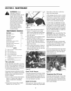
3. Attach thecable adjuster (A,Figure2-9)
to the bracket on the right-side handlebar.
Usetwo 1/2"wrenches to loosen the two
jam nuts (B)just enoughto slidethe cable
adjuster ontothe bracket.Then handtight-
enthe jam nuts.
NOTE: The Wheel Gear Lever will be
installed later in this procedure.
Figure2-9