


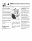

WARNING: Beforeinspecting, cleaning or servicing the machine,shut off engine,wait for all
moving partsto come to a completestop, disconnectspark plug wire and move wire awayfrom
spark plug. Failureto follow these instructions canresult in serious personalinjury or property
damage.
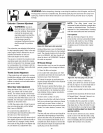
Carburetor / Governor Adjustment
,_ WARNING: Operators
shall nottamper with theengine
governor settings;the governor
controls the maximum safe
operating speedto protect the
engineandall moving parts
from damagecausedby
overspeed.Authorizedservice
shall be sought if a problem
exists.
Thecarburetor wasadjusted atthe factory
for best operatingspeed. Referto the sep-
arate EngineOwner's Manualfor any ad-
justment information or seeyour
authorizedengine service dealer.
The governor controls the maximum safe
operating speedand protects the engine
andall moving parts from damagecaused
by overspeeding. Donot tamper with the
enginegovernor settings. Seekauthorized
service if a problem exists.
Throttle Control Adjustment
If the engine does not respond to various
throttle lever settings, referto the separate
EngineOwner's Manualfor service infor-
mation or contact your localauthorizeden-
gine service dealer.
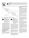
Wheel Gear Cable Adjustment
When theWheel GearLever is in DISEN-
GAGE,the wheels will roll freely (free-
wheel). Thewheelsshould not roll freely
when thelever is in ENGAGE.If the wheels
roll freely whenthe Wheel GearLever is in
ENGAGE,the wheel gearcable needsto be
adjustedas described below.
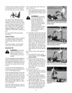
1. With the engine shut off and the spark
plug wire disconnected, put the Wheel
GearLever in ENGAGE.
2. Loosen the top adjustment nut
the wheelgearcable bracketlocatedonthe
left side rearof the transmission.
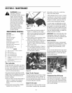
3. Push wheelgearcable (B) downand roll
tiller slightly forward or backward until ec-
centric lever (C) engages(locks) wheels.
Hold cablein that position and tighten top
(A) and bottom (D)adjustment nuts.
Figure5-5: Wheel gear cable assembly.
4. MoveWheel GearLeverto ENGAGEand
DISENGAGEseveraltimes to check adjust-
ment. Thewheelsshould not roll whenthe
lever is in ENGAGE,but they should roll
when the leveris in DISENGAGE.Readjust
the cable as required.
OffSeasonStorage
Whenthe tiller won't beused for extended
periods, prepareit for storage asfollows:
1. Cleanthetiller and engine.
2. Do routine tiller lubrication (see Tiller
Lubrication) andcheck for loose partsand
hardware (see CheckHardware).
3. Protect the engine by performing the
enginestorageinstructions inthe separate
EngineOwner's Manual.
NOTE:Besure to protect the fuel lines,car-
buretor and fuel tank from gum deposits
by removing fuel or by treating fuel with a
fuel stabilizer (follow engine manufactur-
er's recommendations).
4. Store unit in a clean, dry area.
5. Neverstore thetiller with fuel in the fuel
tank in an enclosedareawhere gasfumes
could reach an open flame or spark, or
where ignition sources are present (space
heaters, hot water heaters,furnaces, etc.).
Tines
Thetines will wear with use andshould be
inspected atthe beginning ofeachtilling
seasonandafter every30 operatinghours.
Tinescan be replacedindividually or asa
complete set. Neverinspect or servicethe
tines unlessthe engineis stopped andthe
spark plug wire is disconnected.
18
NOTE: The tiller hood must be
removed to take off either a single tine
holder or individual tines. The hood is
secured to the transmission housing
with two rear bolts and two front bolts.
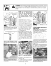
Tine Inspection
With use,the tines (Figure 5-6) will be-
comeshorter, narrower and pointed. Badly
worn tines will result in a loss of tilling
depth and reducedeffectivenesswhen
chopping up andturning under organic
matter.
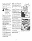
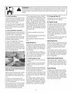
RemovingandInstalling
Figure5-6:Fourfine gangs:twoperside.
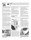
1. Usea 9/16" socket,6" extension, a
ratchet, and a 9/16" box wrench to loosen
the nut (A, Figure5-7) and bolt (B)that se-
cure the tine holderto the tine shaft.
2. Usea rubber mallet to tap the tine hold-
er loose.
3. Slidethe tine assemblyoff thetine shaft.
4. RepeatSteps 1-through-3 aboveto re-
move the othertine assembly.
5. Installing the tine assembly is simply
the reverseof its removal. Besure thecut-
ting edges face sothey will enterthe soil
first whenthe tiller is moving forward- this
meansthe cuttingedgesface towardthe
operator position.
First be sureto removeany rust, uneven
spots or burrs from the tine shaft, using
fine sandpaper.Thengreasethe tine shaft
before reinstalling the tine assemblies.
Tightenthe hardware very securely.