


,_ WARNING: Beforeinspecting, cleaningor servicing the machine,shut off engine, wait for all
moving partsto come to a completestop, disconnectspark plug wire and move wire awayfrom
spark plug. Failureto follow these instructions canresult in serious personalinjury or property
damage.
C
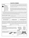
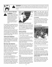
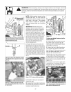
SHAFT
ENGINE
I_ ENOTES CUTTING EDGE IOF TINE
D
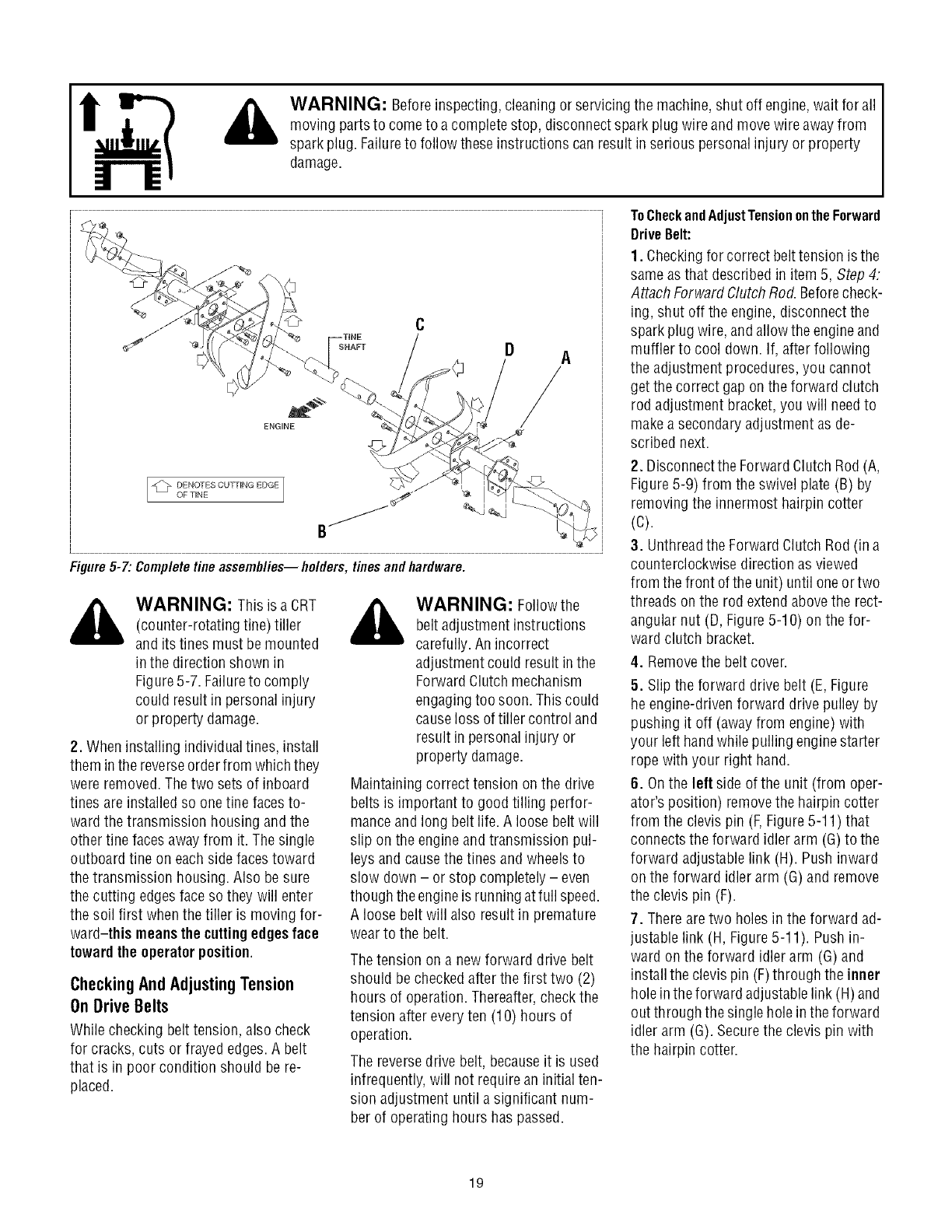
Figure5-7:Completetineassemblies--holders, tinesandhardware.
_b ARNING: This is a CRT
(counter-rotating tine) tiller
and its tines must be mounted
in the direction shown in
Figure5-7. Failureto comply
could result in personal injury
or property damage.
2. When installing individual tines, install
them inthe reverseorder from which they
were removed.The two sets of inboard
tines are installed so one fine facesto-
ward the transmission housing and the
other fine faces awayfrom it. Thesingle
outboard tine on eachside facestoward
the transmission housing. Also be sure
the cutting edges face sothey will enter
the soil first whenthe tiller is moving for-
ward-this meansthe cuttingedgesface
toward the operator position.
CheckingAndAdjustingTension
OnDriveBelts
While checking belt tension, alsocheck
for cracks, cuts or frayed edges.A belt
that is in poor condition should be re-
placed.
_ ARNING: Follow the
belt adjustment instructions
carefully. An incorrect
adjustment could result in the
ForwardClutch mechanism
engagingtoo soon. This could
causeloss oftiller control and
result in personalinjury or
property damage.
Maintaining correct tension on the drive
belts is important to good tilling perfor-
manceand long belt life. A loose belt will
slip on the engine and transmission pul-
leys and causethe tines and wheelsto
slow down - or stop completely - even
though the engineis runningat full speed.
A loose beltwill also result in premature
wear to the belt.
Thetension on a newforward drive belt
should be checkedafter the first two (2)
hours of operation.Thereafter,check the
tension after every ten (10) hours of
operation.
The reversedrive belt, becauseit is used
infrequently, will not requirean initial ten-
sion adjustment until a significant num-
ber of operatinghours has passed.
ToCheckandAdjustTensionontheForward
DriveBelt:
1. Checkingfor correct belttension is the
sameas that described in item 5, Step 4:
Attach Forward ClutchRod. Beforecheck-
ing, shut off the engine,disconnect the
spark plug wire, andallow the engineand
muffler to cool down. If, after following
the adjustment procedures, you cannot
get the correct gap on the forward clutch
rod adjustment bracket, you will needto
makea secondaryadjustment asde-
scribed next.
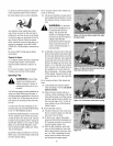
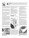
2. Disconnectthe ForwardClutch Rod (A,
Figure 5-9) from the swivel plate (B) by
removing the innermost hairpin cotter
(C).
3. Unthreadthe Forward ClutchRod (in a
counterclockwise direction as viewed
from the front of the unit) until oneor two
threads on the rod extendabovethe rect-
angular nut (D, Figure5-10) on the for-
ward clutch bracket.
4. Removethe belt cover.
5. Slip the forward drive belt (E, Figure
he engine-drivenforward drive pulley by
pushing it off (awayfrom engine) with
your left handwhile pulling enginestarter
rope with your right hand.
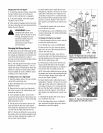
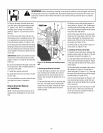
6. Onthe left side ofthe unit (from oper-
ator's position) removethe hairpin cotter
from the clevis pin (F,Figure5-11) that
connectsthe forward idler arm (G)to the
forward adjustable link (H). Push inward
on the forward idler arm (G) and remove
the clevis pin (F).
7. Thereare two holes in the forward ad-
justable link (H, Figure5-11). Pushin-
ward on the forward idler arm (G) and
install theclevis pin (F)through the inner
holein theforward adjustablelink (H)and
out through the singlehole in theforward
idler arm (G). Securethe clevis pin with
the hairpin cotter.
19