


3.Tomovethetillerinreverse,firststopall
forwardmotion.Liftupthehandlebarsun-
tilthetinesclearthegroundandpullthe
ReverseClutchleverout.
Thewheelswillrotateinareversedirection
aslongastheleverisheldinREVERSE.To
stopthewheelsandtines,releasethelever
anditwillreturntoNEUTRAL.Neverat-
tempt totill while movingin reverse di-
rection.
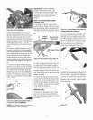
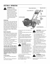
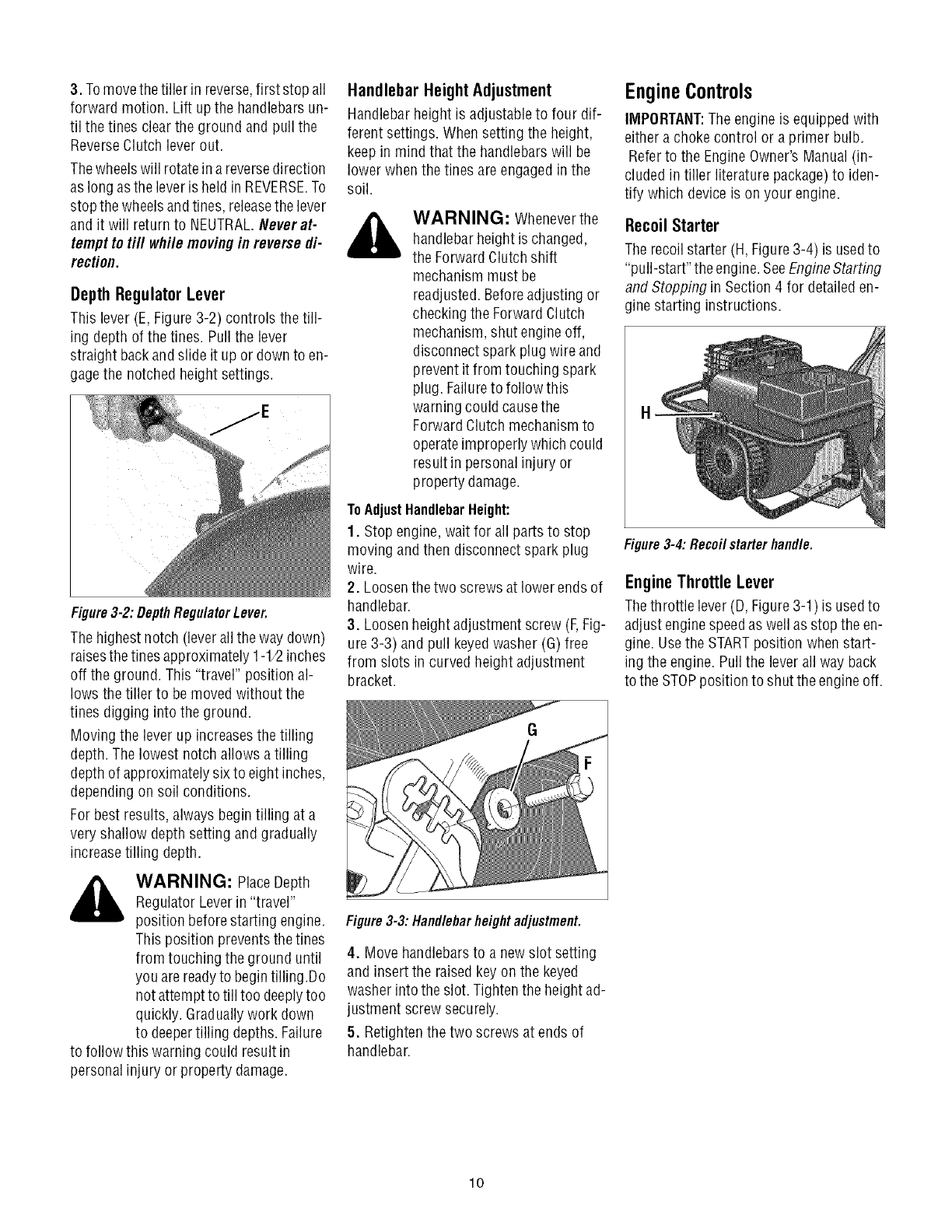
DepthRegulatorLever
This lever (E,Figure 3-2) controls the till-
ing depth of the tines. Pullthe lever
straight backand slide it up or downto en-
gagethe notched height settings.
Figure3-2:DepthRegulatorLever.
The highest notch (lever all theway down)
raisesthe tines approximately1-1/2inches
off the ground. This "travel" position al-
lows the tiller to bemoved without the
tines digging into the ground.
Moving the leverup increasesthetilling
depth. Thelowest notch allows a tilling
depth of approximatelysix to eight inches,
dependingon soil conditions.
For best results, alwaysbegin tilling at a
very shallow depth setting and gradually
increasetilling depth.
,_ WARNING: PlaceDepth
Regulator Leverin "travel"
position before starting engine.
This position preventsthetines
from touching the ground until
you are readyto begintilling .Do
not attempt to till too deeplytoo
quickly. Graduallywork down
to deepertilling depths.Failure
to follow this warning could result in
personal injury or property damage.
Handlebar HeightAdjustment
Handlebar heightis adjustableto four dif-
ferent settings. Whensetting the height,
keep in mind that the handlebarswill be
lower when the tines areengagedin the
soil.
WARNING: Wheneverthe
handlebarheight is changed,
the Forward Clutchshift
mechanism must be
readjusted. Beforeadjusting or
checking the ForwardClutch
mechanism, shut engine off,
disconnect spark plug wire and
prevent itfrom touching spark
plug. Failureto follow this
warning could causethe
ForwardClutch mechanismto
operateimproperly which could
result in personal injury or
property damage.
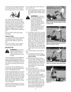
ToAdjustHandlebarHeight:
1. Stop engine, wait for all parts to stop
moving andthen disconnectspark plug
wire.
2. Loosenthetwo screws at lower endsof
handlebar.
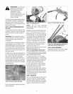
3. Loosenheight adjustment screw (F,Fig-
ure 3-3) and pull keyedwasher (G)free
from slots in curved height adjustment
bracket.
Figure3-3: Handlebarheight adjustment.
4. Move handlebarsto a newslot setting
and insert the raisedkeyon the keyed
washer intothe slot. Tightenthe height ad-
justment screw securely.
5. Retighten the two screws atends of
handlebar.
EngineControls
IMPORTANT:The engineis equipped with
either a choke control or a primer bulb.
Referto the EngineOwner's Manual(in-
cluded in tiller literature package)to iden-
tify which deviceis on your engine.
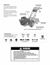
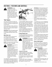
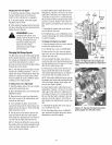
Recoil Starter
The recoilstarter (H, Figure3-4) is usedto
"pull-start" theengine. SeeEngineStarting
and Stopping in Section4 for detailed en-
gine starting instructions.
H
Figure 3-4: Recoil starter handle.
EngineThrottle Lever
Thethrottle lever(D, Figure3-1) is usedto
adjust enginespeedas well asstop theen-
gine. Usethe STARTposition whenstart-
ing the engine. Pullthe lever all way back
to the STOPposition to shut the engineoff.
lO