


WARNING: Beforeinspecting, cleaning or servicing the machine,shut off engine,wait for all
moving partsto come to a completestop, disconnectspark plug wire and move wire awayfrom
spark plug. Failureto follow these instructions canresult in serious personalinjury or property
damage.
front of the unit (not the operator's posi-
tion). If the belttension iscorrect, reinstall
the belt cover and secureit with the two
nuts.
• If the guide mark is aligned with the
guide pin,or movesto the right sideof the
guide pin,then the belt is too looseandthe
tension must be readjustedas described
next.
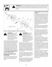
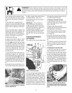
3. The reverseidler pulley (L,Figure5-13)
regulatesthe tension that is appliedto the
reversedrive belt (P). The following ad-
justment will allowthe reverseidler pulley
to apply more tension to a loose belt.
4. Removethe belt cover.
5. Slipthe reversebelt (P,Figure5-13) off
the engine-driven reverse (upper) pulley.
6. Onthe right side ofthe unit (asviewed
from operator's position), removethe hair-
pin cotter from the clevis pin (R, Figure 5-
13) that connectsthe reverseidler arm(K)
to the reverseadjustable link. Push inward
on the reverseidler arm (K) and remove
the clevis pin (R).
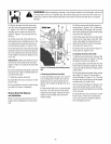
7. There aretwo holesin the reversead-
justable link (S, Figure5-15). Pushinward
on the reverseidler arm (K) and installthe
clevis pin (R)through the inner holein the
reverseadjustablelink (S) andoutthrough
the single hole in the reverseidler arm (K).
Securethe clevis pin with the hairpin cot-
ter.
8. Reinstallthe reversebelt (P,Figure5-13)
onthe reverse(upper) pulley,making sure
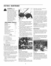
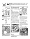
Figure5-15:Installingclevispin ininsidehole
ofreverseadjustablelink.
the belt is located to the inside of the re-
verse idler pulley (L, Figure 5-13).
9. Reinstallthe belt cover and secure it
with the two nuts.
IMPORTANT: If, in future tests for
reversebelttension, theguide mark
should againalign with or moveto the
right side of theguide pin, it meansthat
the reversebelt is worn beyond
adjustment. Beforeinstalling a new belt,
you must return the clevis pin tothe
OUTSIDEhole in the reverseadjustable
link.
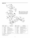
Forward Drive Belt Removal
and Installation
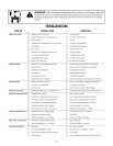
This model hastwo forward speeds(High
D B
FRONT.-II_
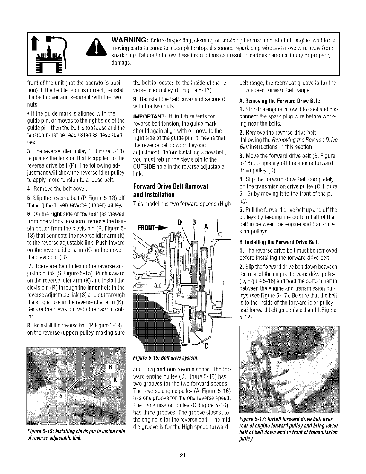
Figure5-16: Belt drivesystem.
belt range; the rearmost groove isfor the
Low speedforward belt range.
A. Removingthe ForwardDriveBelt:
1. Stop the engine,allow it to cool and dis-
connect the spark plug wire before work-
ing nearthe belts.
2. Removethe reversedrive belt
following the Removingthe ReverseDrive
Beltinstructions in this section.
3. Movethe forward drive belt (B,Figure
5-16) completely off the engineforward
drive pulley (D).
4. Slip the forward drive belt completely
off thetransmission drive pulley (C,Figure
5-16) by moving it to the front of the pul-
ley.
5. Pullthe forward drivebelt upand off the
pulleys by feeding the bottom half of the
belt in betweenthe engine andtransmis-
sion pulleys.
B.Installingthe ForwardDriveBelt:
1. The reversedrive beltmust beremoved
before installing the forward drive belt.
2. Slipthe forward drivebeltdown between
the rearof the engineforward drivepulley
(D,Figure5-16) andfeedthe bottom half in
betweenthe engineand transmissionpul-
leys(see Figure5-17). Besurethatthe belt
is to the insideof the forward idler pulley
andforward beltguide (seeJ and I, Figure
5-12).
and Low) and one reversespeed.Thefor-
ward engine pulley (D, Figure5-16) has
two grooves for the two forward speeds.
The reverseenginepulley (A, Figure5-16)
has onegroove for the one reversespeed.
The transmission pulley (C, Figure5-16)
has three grooves. Thegroove closest to
the engineis for the reversebelt. Themid-
dle groove is for the High speed forward
Figure5-17: Install forwarddrive belt over
rear of engineforwardpulley and bringlower
haft of belt downand in frontoftransmission
pulley.
21