


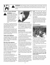

,_ WARNING: Beforeinspecting, cleaningor servicing the machine,shut off engine, wait for all
moving partsto come to a completestop, disconnectspark plug wire and move wire awayfrom
spark plug. Failureto follow these instructions canresult in serious personalinjury or property
damage.
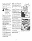
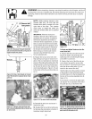
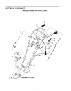
C (E) Removebelt
Figure 5-9: Disconnect ForwardClutch Rod
and moveforward drivebelt out of groove in
engine forward drivepulley.
Figure 5-10: Oneor two threadson Forward
Clutch Rod should he exposed aboverectan-
gular nut.
NOTE: While pushing inward on the
forward idler arm, be sure that the
forward drive belt is moved off to the
right side of the tiller. This creates
more room to install the clevis pin
when the forward idler arm is 3ushed
inward.
IMPORTANT:When the clevis pin Is
installed in the inner hole ofthe forward
adjustablelink, the number of additional
belt tension adjustmentsare limited. If,
with future tension adjustments, you find
that you cannot screwtheforward clutch
rod anyfarther into the rectangularnut on
the forward clutch bracket,it meansthat
the forward drive belt must be replaced.
Beforedoing so, the clevispin must be
returnedto the OUTSIDEhole inthe
forward adjustablelink.
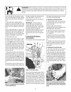
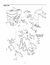
8. Replacethe forward drive belt in the
High speedgroove (groove closest to en-
gine) or the Lowspeed groove (rearmost)
groove ofthe enginedrive pulleyandinthe
matching groove of the transmission pul-
ley. Besure the belt is to the inside of the
wire formed beltguide (I, Figure5-12) and
to the inside of the forward drive idler pul-
ley (J).
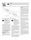
Figure 5-12: Topview of beltsand pulleys.
Figure5-13
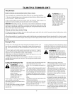
ToCheckand AdjustTensiononthe Re-
verse DriveBelt:
1. Removethe belt cover after first shut-
ting off the engine,disconnecting the
spark plug wire, and allowing the engine
and muffler to cool down.
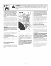
2. Stand at the front of the tiller and use
your left handto push the reverseidler
arm (K, Figure 5-13) inward as far as pos-
sible (the reverseidler pulley [L] is at-
tached to the reverseidler arm).
Hold theidler arm in this position and look
at the position of the belt tension guide
mark (M, Figure5-14) that isstamped into
the face of the reverseadjustable link (N,
Figure 5-14).
• The tension is correct if the guide mark
(M, Figure5-14) is anywhereto the left of
the guide pin (0), as viewed from the
Figure5-11: Remove clevispin fromouter
hole inforwardadjustablelinkand movetoin-
ner holein link.
9. Reinstallthe belt cover and secure it
with the two nuts.
10. Readjustthe forward drivebelt tension
by following the instructions in Section 3:
HandlebarHeight Adjustment.
Figure5-14: Whilepushingreverseidler arm #l-
ward,standat engineendandcheckpositionof
guidemark(M) andguidepin (0).
2O