


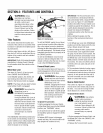

SECTION2: ASSEMBLY
WARNING: Toprevent
personal injury or property
damage,do not start the engine
until all assemblysteps are
complete andyou have read
and understandthesafety and
operating instructions in this
Manual.
Introduction
Carefully follow these assemblysteps to
correctly prepareyour tiller for use. It is
recommendedthatyou readthis Sectionin
its entirety before beginning assembly.
Inspect unit
Inspect the unitand carton for damageim-
mediatelyafter delivery.Contactthe carrier
(trucking company) if you find or suspect
damage. Inform them of the damageand
request instructions for filing a claim. To
protect your rights, put your claim in writ-
ing and mail a copyto the carrierwithin 15
days after the unit has beendelivered.
Contact usat the factory if you needassis-
tance in this matter.
Unpackingand Assembly
Instructions
STEP1:UNPACKINGINSTRUCTIONS
1. Removeany card-board inserts and
packaging materialfrom the carton. Re-
move anystaples from the bottom ofthe
carton and removethe carton.
2. Cutthe large,plastictie strapthat se-
curesthe transmissiontube to the shipping
pallet. Leavethe handlebarson top ofthe
tiller to avoid damagingany cables.
3. A bag with loosehardware is inside the
literature envelope.Checkthe contents
againstthe following list and Figure2-1.
Contactyour local dealeror the factory if
any items are missing or damaged.
NOTE:For electric start units, a second
hardware bag is located nearthe battery.
4. The tiller is heavy.Youshould not at-
tempt to removeit from the shipping plat-
form until instructed to do so in these
"Assembly" steps.
HardwareBagPartsList
Ref. Qty. Description
1 2 3/8-16 x 1" HexHd. Screw
2 1 KeyedWasher
3 1 Wheel GearLever Knob
4 1 Height Adjustment Flange
(SeeFigure 2-2)
5 2 3/8" FlatWasher
6 2 #10 Lockwasher
7 2 3/8"-16 Nylock Lock Nut
8 2 #10-32 x 1/2" Rnd Hd Screw
9 2 #10-32 Nut
18 1 CotterPin (not used)
11 4 PlasticTie Strap (2 not used)
Tools/ MaterialsNeeded
for Assembly
(1) 3/8" open-endwrench*
(2) 9/16" open-endwrench*
(1) 7/8" open-endwrench"
(1) Scissors (to trim plasticties)
(1) Ruler
(1) Small board (totap plastic knob on
lever)
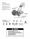
(1) Tire pressure gauge
(1) Cleanoil funnel
(1) Clean,high-quality motor oil. Referto
the separateEngineOwner's Manual
for motor oil specificationsand quan-
tity required.
* Adjustable wrenchesmay be used.
IMPORTANT: Motor oil must beaddedto
the enginecrankcasebefore the engine is
started. Followthe instructions inthis
"Assembly" Sectionand in the separate
EngineOwner'sManual.
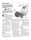
NOTE: LEFT and RIGHT sides of the
tiller are as viewed from the
operator's position behind the
handlebars.
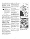
STEP2: ATTACHHANDLEBARS
1. Cutthe large, plastic cableties that se-
cure the handlebarends to the handlebar
mounting tabs onthe transmission top
cover.
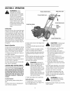
2. Gentlylift handlebar(do not overstretch
attachedcable) and placehandlebarcross-
brace (B, Figure2-3) in front of curved
height adjustment bracket (C).
4
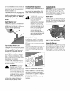
O@ 8
7 10 11
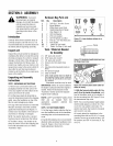
Figure2-1:Loosehardware(shownin re-
ducedsize).
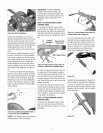
Figure2-2: Handlebarheightadjustmentuses
the flange headscrew.
Figure2-3:Forwardclutchcontrolcablenot
shownforclarity.
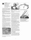
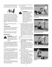
3. With the forwardclutchcable (N, Fig-
ure 2-4) onthe inside ofhandlebar,posi-
tion the handlebarends on the outside of
the two mounting tabs (M, Figure2-3) on
the transmission top cover.
NOTE:The curved handlebarheightadjust-
ment bracket appearsas shown in C, Fig-
ure 2-3 for non-electric start units. For
electric start units, the bracket isloosened
and moved to one side.
4. Loosely attachthe handlebarsto the
mounting tabs with two 3/8-16 x 1"screws
(headsof screws goto inside of tabs), 3/8"
flat washers and 3/8"-16 lock nuts (O,Fig-
ure2-4).