


Incorrect cable adjustment could cause
the wheels and tines to rotate unexpect-
edly. Follow adjustment procedures
carefully. Failure to do so could result
in personalinjuryorpropertydamage.
4. Checkfor correct spring/cable tension
as instructed in Section 5, Checkingand
Adjusting Forward ClutchBelt Tension.
5. Whentension is correct, tighten the
two jam nuts (B) securely.
STEP 5: CHECKTRANSMISSION
GEAROIL LEVEL
Thetransmission was filled with gearoil
at the factory. However,be sure to check
the oil levelat this time to make certain it
is correct.
IMPORTANT:Do not operatethe tiller if
the gear oil level is low. Doing so will
result in severedamageto thetransmis-
sion components.
1. With thetiller on levelground, pull the
Depth Regulator Lever(R, Figure2-13)
backand then slide it to the second notch
from thetop. NOTE:Ifthe leverdoes not
move, lift thetine hood flap and look for a
plastictie securing the leverin place. Cut
and removethe tie.
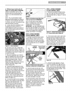
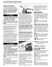
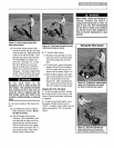
2. Removethe oil levelcheck plug (M,
Figure2-10) on the left-side of the trans-
mission. (Dueto dried paint onthe plug
threads, it may require some force to
removethe plug thefirst time.) The gear
oil levelis correct if oil starts to flow out
of the hole asthe plug is removed. If so,
securelyreinstall the plug.
Figure2-1O:Gearoilleve/checkplug.
3. If oil doesnot flow from the check
hole,add oil as follows:
NOTE:Donot useautomatic transmission
fluid or motor oil in thetransmission.
{a) Cleanareaaround thefill hole (N,
Figure2-11) and unscrewgear oil fill
plug.
Figure2-11: Addinggear oil,
(b) If adding only a few ounces of gear
oil, useAPI ratedGL-4 or GL-5 gear oil
havinga viscosity of SAE140, SAE85W-
140 or SAE80W-90. If refilling an empty
transmission, useonly GL-4 gear oil
havinga viscosity of SAE85W-140 or
SAE140.
(c) Usinga cleanfunnel, slowly add gear
oil until itflows from the gearoil level
checkhole (N, Figure2-11).
(d) Reinstalland tighten securelythe gear
oil fill plug (M, Figure2-10).
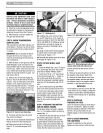
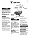
STEP 6: ATTACHWHEEL GEAR
LEVER
1. Insertthe WheelGearLever(P, Figure
2-12) up through the slot in the control
panelthat is labeled"WHEELGEAR."
2. Inserttwo #10-32 x 1/2" round head
screws down through the "+" marks on
thecontrol paneldecaland securely
attachthe wheelgear mounting bracket
using two #10 Iockwashersand #10-32
nuts.
3. Usea small board to tap the Wheel
GearLeverknob securelyonto the lever.
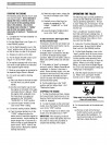
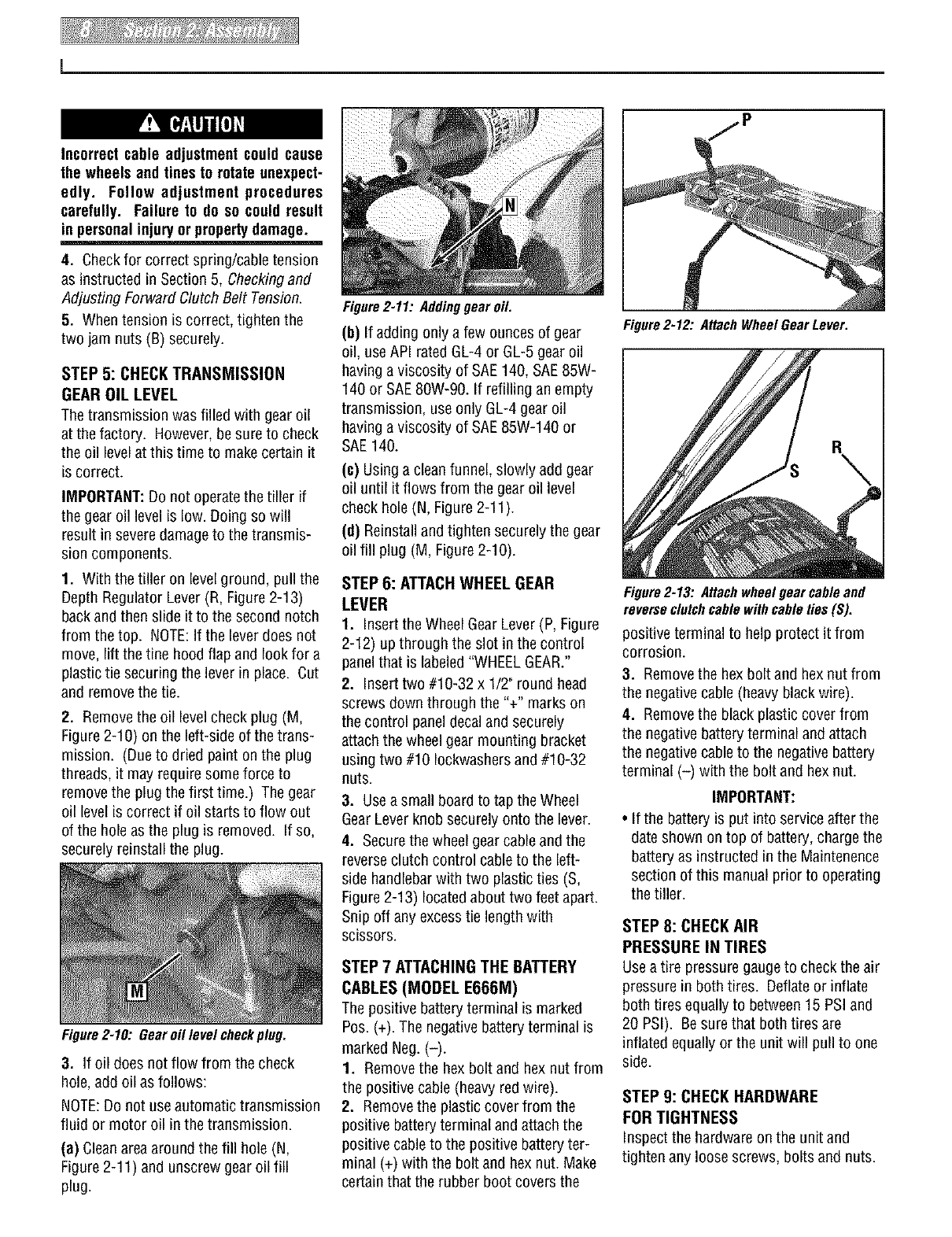
4. Securethe wheel gearcableand the
reverseclutch control cableto the left-
side handlebarwith two plasticties (S,
Figure2-13) locatedabout two feet apart.
Snip off anyexcesstie lengthwith
scissors.
STEP 7 ATTACHINGTHE BATTERY
CABLES(MODELE666M)
Thepositive batteryterminal is marked
Pos. (+). The negativebatteryterminal is
marked Neg. (-).
1. Removethe hex bolt and hexnut from
the positive cable (heavyred wire).
2. Removethe plasticcover from the
positive batteryterminal and attachthe
positive cableto the positive batteryter-
minal (+) with the bolt and hexnut. Make
certainthat the rubber boot coversthe
Figure2-12: AttachWheel GearLever,
Figure2-13: Attachwheelgearcableand
reverseclutchcablewithcableties(S).
positive terminal to help protect itfrom
corrosion.
3. Removethe hexbolt and hexnut from
the negativecable(heavy blackwire).
4. Removethe black plastic cover from
the negativebatteryterminal and attach
the negativecableto the negative battery
terminal (-) with the bolt and hexnut.
IMPORTANT:
• If the batteryis put into serviceafter the
dateshown on top of battery, chargethe
batteryas instructed in the Maintenence
section of this manual prior to operating
thetiller.
STEP 8: CHECKAIR
PRESSURE IN TIRES
Usea tire pressuregauge to checkthe air
pressure in both tires. Deflateor inflate
both tires equallyto between15 PSI and
20 PSI). Besurethat both tires are
inflated equally or the unit will pullto one
side.
STEP 9: CHECK HARDWARE
FOR TIGHTNESS
Inspectthe hardwareon the unit and
tighten any loose screws, bolts and nuts.