


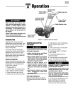
Assembly
To prevent personal injury or property
damage,do not startthe engineuntil all
assembly steps are complete and you
havereadand understandthesafetyand
operatinginstructionsin this Manual.
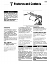
INTRODUCTION
Carefullyfollow these assembly stepsto
correctly prepareyour tiller for use. It is
recommendedthat you read this Section
in its entirety before beginning assembly.
INSPECTUNIT
Inspectthe unit and carton for damage
immediately after delivery. Contactthe
carrier (trucking company) if you find or
suspect damage. Inform them of the
damageand request instructions for filing
a claim. To protectyour rights, put your
claim in writing and maila copy to the
carrier within 15 days after the unit has
been delivered.Contact usat the factory if
you needassistance in this matter.
UNPACKINGANDASSEMBLY
INSTRUCTIONS
STEP 1: UNPACKING INSTRUCTIONS
1. Removeanycardboard insertsand
packaging materialfrom the carton.
Removeany staplesfrom the bottom of
the carton and removethe carton.
2. Cutthe large,plastictie strap that
securesthetransmission tube to theship-
ping pallet. Leavethe handlebarson top
of the tiller to avoid damaginganycables.
3. A bag with loose hardwareis inside
the literature envelope. Checkthe con-
tents against thefollowing list and Figure
2-1. Contactyour local dealeror the
factory if any items are missing or
damaged.
NOTE: Forelectric start units, a second
hardware bag is located nearthe battery.
4. Thetiller is heavy. You should not
attempt to remove it from the shipping
platform until instructed to do so in these
"Assembly" steps.
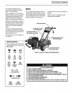
HARDWARE BAG PARTSLIST
Fig.
Ref. Qty. Description
1 2 3/8-16 x 1" HexHd. Screw
2 1 KeyedWasher
3 1 WheelGearLeverKnob
4 1 Height Adjustment Flange
Screw (SeeFigure2-1A)
5 2 3/8" FlatWasher
6 2 #10 Lockwasher
7 2 3/8"-16 Nylock Lock Nut
8 2 #10-32 x 1/2" RoundHd.
Screw
9 2 #10-32 Nut
10 1 Cotter Pin (not used)
11 4 PlasticTie Strap (2 not used)
Tools/Materials Needed
for Assembly
(1) 3/8"open-end wrench*
(1) 7/16" open-endwrench* (electric
start unit only)
(2) 9/16" open-endwrench*
(1) 7/8" open-endwrench or 8" long
adjustablewrench
(1) Scissors (to trim plasticties)
(1) Ruler
(1) Small board (to tap plasticknob on
lever)
(1) Tire pressuregauge
(1) Cleanoilfunnel
(1) Clean,high-quality motor oil. Refer
to the separateEngineOwner's
Manualfor motor oil specifications
and quantity required.
* Adjustable wrenches may be used.
IMPORTANT:Motor oil must beadded to
the enginecrankcase beforethe engine is
started. Followthe instructions inthis
"Assembly" Sectionand in the separate
EngineOwner's Manual.
NOTE:LEFTand RIGHTsidesof the tiller
areas viewedfrom the operator's posi-
tion behindthe handlebars.
STEP 2: ATTACHHANDLEBARS
1. On electric start units, remove one
screw and Iockwasherfrom the curved
'T
600
7_ 8_' _ _9
10 _.
11
Figure2-1:Loosehardware(shownin
reducedsize).
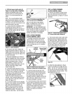
Figure2.1A Hand/ebarheightadjustment
usestheflangeheadscrew.
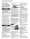
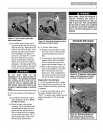
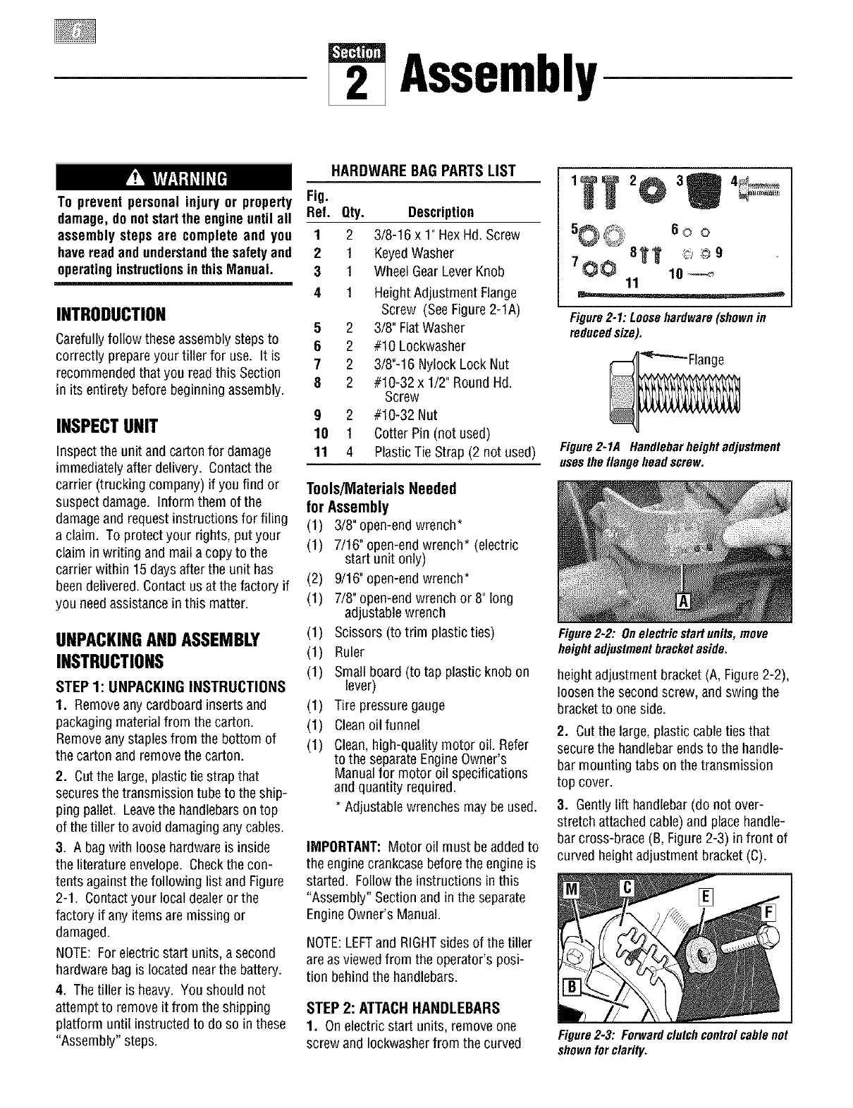
Figure2-2: Onelectricstartunits,move
heightadjustmentbracketaside.
heightadjustment bracket (A, Figure2-2),
loosenthe second screw, and swing the
bracketto oneside.
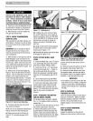
2. Cut the large,plastic cableties that
securethe handlebarendsto the handle-
bar mounting tabs on thetransmission
top cover.
3. Gently lift handlebar(do not over-
stretch attachedcable)and placehandle-
bar cross-brace (B, Figure2-3) in front of
curved height adjustment bracket (C).
Figure2-3: Forwardclutchcontrolcablenot
shownforclarity.