


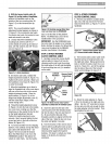
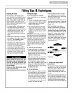
4. Withtheforwardclutchcable (N,
Figure2-4) on the insideofhandlebar,
position the handlebarendson the
outside of the two mounting tabs (M,
Figure2-3) on the transmission top
cover.
NOTE:Thecurved handlebarheight
adjustment bracketappearsasshown in
C,Figure2-3 for non-electric start units.
Forelectric start units, the bracket is loos-
enedand moved to one side.
5. Loosely attachthe handlebarsto the
mounting tabs with two 3/8-16 x 1"
screws (headsof screws go to insideof
tabs), 3/8" flat washersand 3/8"-16 lock
nuts (O,Figure2-4).
Figure24: Attachhandlebars.
6. On electricstart units, reattachthe
heightadjustment bracket (A,Figure2-2).
Tighten both screws securely. Makesure
the handlebarcross-brace (B, Figure2-3)
is under the bracket.
7. Move the handlebarsup or down to
align the threadedhole in the cross-brace
with one of thefour slots in the curved
heightadjustment bracket. Placethe
keyedwasher (E,Figure2-3) on the
flange head heightadjustment screw (F)
with the raisedkeys (edges)of the
washer facing down.
8. Threadthe heightadjustment screw
(F, Figure 2-3) into the hole in the handle-
bar cross-brace, making surethat the
raisedkeyson thewasher fit into the slot
on the height adjustment bracket.
Tighten the heightadjustment screw
securely. Next, securelytighten the two
screwsand nuts in the ends ofthe han-
dlebar (M, Figure2-3).
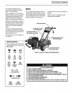
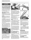
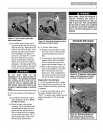
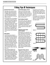
9. To removethe tiller from its shipping
platform, first carefully unwrapthe wheel
gearcable (with attachedlever- see
Figure2-5) from around the chassis.
Move theWheel Gear Lever(G) to the
DISENGAGEposition--this allows the
wheels to rotatefreely. Usethe handle-
g
#
Figure25: CarefullyunwrapWheelGear
LeverandmovelevertoDISENGAGE.
barsto roll the tiller off the platform.
NOTE:TheWheelGearLeverwill be
installed later in this procedure.
IMPORTANT: Usethe DISENGAGEposi-
tion only when the engineis not running.
Beforestarting the engine,theWheel Gear
Levermust beplaced in the ENGAGE
position (seeSection 3 for details).
STEP3: ATTACHREVERSE
CLUTCH CONTROL CABLE
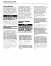
1. Carefullyunwrap the reverseclutch
control cable(H, Figure2-6) from its
shipping position and route it upalong
the insideedge ofthe left side handlebar.
A knoband large hexnut (I) is installed
on the cable.
LeftSide ReverseClutch
Handlebar ControlKnob
Figure2-6."Attachreverseclutchcontrol
assemblytoslottedholeinhandlebarpanel.
2. Insert the cableinto the slot in the
control paneland fit the threadedassem-
bly into the hole in theslot (seeFigure2-
6). Besurethat the flat sideof the
threaded assemblyis aligned with the flat
side ofthe hole. Slidethe hex nut (I) up
the cableand tighten it securely.
3. Testthe function of the reverseclutch
control cableby pulling the knob out and
releasingit. Theknob should returnto its
neutral position against the tapered
bushing. If it doesn't, contact your local
dealer or thefactory for technical
assistance.
STEP 4: ATTACHFORWARD
CLUTCH CONTROLCABLE
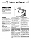
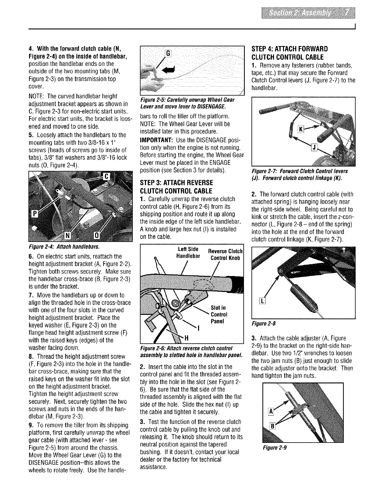
1. Removeanyfasteners (rubber bands,
tape, etc.)that may secure the Forward
Clutch Control levers (J, Figure2-7) to the
handlebar.
I
Figure2-7: ForwardClutchControllevers
(J). Forwardclutchcontrollinkage(K).
2. Theforward clutch control cable(with
attachedspring) is hanging loosely near
the right-side wheel. Beingcareful not to
kink or stretch the cable, insert the z-con-
nector (L, Figure2-8 - end of the spring)
into the hole at the end of theforward
clutch control linkage(K, Figure2-7).
Figure2-8
3. Attach thecableadjuster (A, Figure
2-9) to the bracket on the right-side han-
dlebar. Usetwo 1/2"wrenchesto loosen
thetwo jam nuts (B)just enough to slide
the cableadjuster onto the bracket. Then
hand tighten the jam nuts.
Figure2-9