


Maintenance
Before inspecting, cleaning or
servicingthe machine, shut off engine,
wait for all moving parts to come to a
complete stop, disconnect spark plug
wire and move wire away from spark
plug. Remove ignition key on electric
startmodels.
Failure to follow these instructionscan
resultin seriouspersonalinjuryor prop-
ertydamage.
MAINTENANCESCHEDULE
PROCEDURE ROTES
Check motor oil level 2, 3
Clean engine 2, 7
Checkdrive belt tension 1,4
Check nuts and bolts 1,4
Changemotor oil 1,4, 6
Lubricatetiller 4
Servicefoam pro-cleaner air filter 7
(if so equipped)
Servicepaper air filter (if so equipped) 7
Checkgear oil levelintransmission 1, 5
Checktines for wear 5
Checkair pressure intires 5
Servicespark plug 7
NOTES
1- After first 2 hours of break-in operation.
2 - Beforeeachuse.
3 - Every5 operating hours,
4 - Every 10operating hours,
5 - Every30 operating hours,
6 - More frequently in dustyor dirty conditions,
7 - SeeEngineOwner'sManualforservice
recommendations.
8 - Whichevertimeintervaloccursfirst,
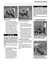
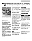
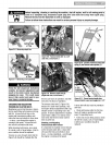
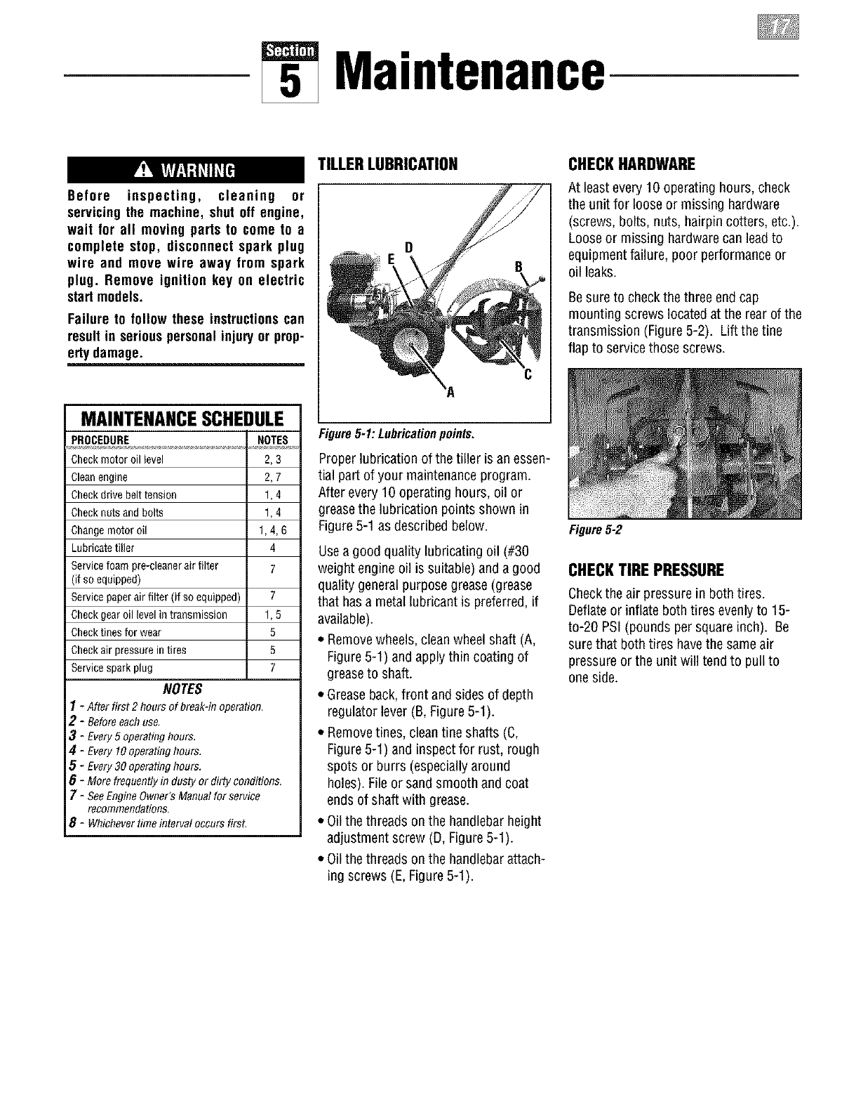
TILLERLUBRICATION
C
Figure5-1: Lubricationpoints.
Proper lubrication of the tiller isan essen-
tial part of your maintenanceprogram.
After every 10 operating hours, oil or
greasethe lubrication points shown in
Figure5-1 asdescribed below.
Usea good quality lubricating oil (#30
weight engine oil is suitable) and a good
quality generalpurpose grease(grease
that hasa metal lubricant is preferred, if
available).
• Removewheels,cleanwheel shaft (A,
Figure5-1) andapply thin coatingof
greaseto shaft.
• Greaseback,front and sides of depth
regulator lever (B,Figure5-1).
• Removetines, cleantine shafts (C,
Figure5-1) and inspectfor rust, rough
spots or burrs (especiallyaround
holes). File or sandsmooth and coat
endsof shaft with grease.
• Oilthe threads on the handlebarheight
adjustment screw (D, Figure5-1).
• Oilthe threads on the handlebarattach-
ing screws (E,Figure5-1).
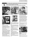
CHECKHARDWARE
At leastevery 10 operating hours, check
the unit for looseor missing hardware
(screws, bolts, nuts, hairpin cotters, etc.).
Looseor missing hardwarecan leadto
equipmentfailure, poor performanceor
oil leaks.
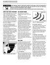
Besure to checkthe threeend cap
mounting screws located atthe rearofthe
transmission (Figure5-2). Lift the tine
flap to servicethose screws.
Figure5-2
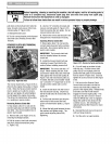
CHECKTIREPRESSURE
Checkthe air pressure in both tires.
Deflateor inflate both tires evenlyto 15-
to-20 PSI(pounds per squareinch). Be
surethat both tires havethe same air
pressure or the unit will tend to pullto
oneside.