Two Stage Snowthrower Drive Systems Manual 3 - 11
Traction Drive Systems
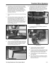
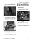
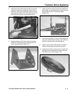
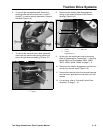
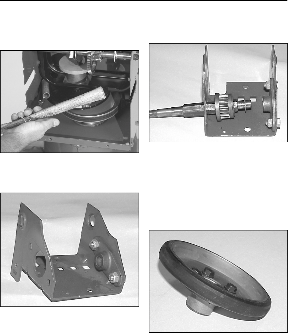
5. Install the friction plate spring into the front frame
assembly. Note some models just have a hole in
the frame. Others have a tab bent outward to hook
the spring into (Figure 100). Hook the lower end of
the spring into the notch in the traction frame.
Figure 100
2773-078
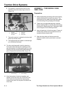
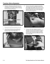
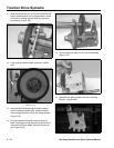
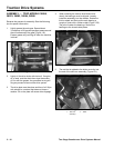
6. Begin assembly of the friction wheel and sliding
bracket by installing the right side (opposite the
friction wheel) bearing (Figure 101).
Figure 101
MVC-862
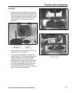
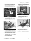
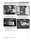
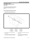
7. Lightly oil the hex shaft. Insert the hex shaft from
the left side, non-threaded end first. Slip the shaft
through the left side of the sliding bracket
(Figure 102).
Figure 102
MVC-864
8. Place the pinion gear on the hex shaft (larger OD
to the left). Add the thrust washer, then insert the
shaft into the previously mounted bearing.
9. Install a thrust washer and the second bearing.
Tighten the bearing mounting bolts securely.
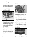
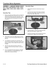
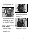
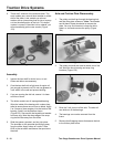
10. Assemble the friction wheel and hub using 4 self-
tapping screws. Note the hub mounts to the flat
side of the friction wheel (Figure 103).
Figure 103
MVC-718


