


Auger Gearbox Service
1 - 10 Two Stage Snowthrower Drive Systems Manual
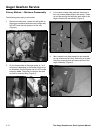
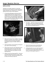
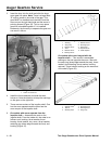
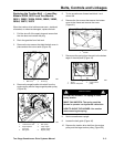
3. Insert the keys into the shaft and slide the large
worm gear into place. Note: There is a large letter
“R” and an arrow on one side of the gear. This
gear MUST be installed such that the R and the
arrow are on the right hand side and the arrow is
pointing forward (Figure 30). This is a two piece
gear that is bonded together. If it is installed
backwards, the forces try to separate the gear and
can result in failure.
Figure 30
30
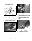
4. Install the thrust washers and slide the case
halves on. Note the direction to keep the markings
on the gear on the right side.
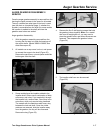
5. There are two versions of the impeller shaft. One
has the worm separate and the other has the
worm as part of the impeller shaft.
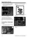
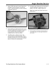
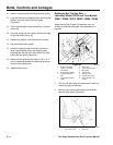
6. On models with worm separate from the
impeller shaft — Assemble the parts on the
impeller shaft. From the inside out, the order is as
follows: seal, bushing, thrust washer, thrust
bearing, thrust washer, key, worm, thrust washer,
retaining ring (sharp edge towards the front) and
bushing (Figure 31).
Figure 31
37-6962
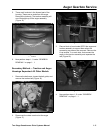
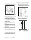
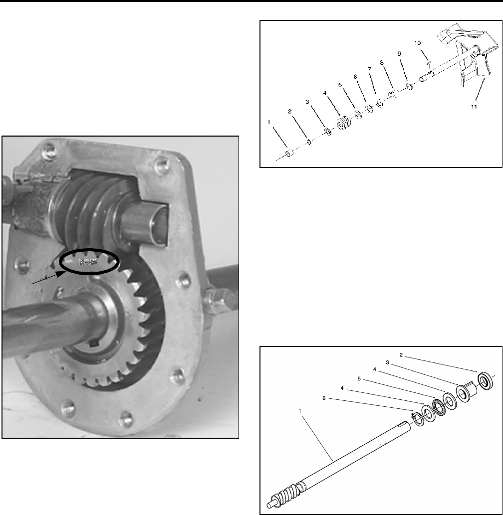
On models with worm integral with the
impeller shaft — This version is assembled
starting on the end opposite the worm. Start with
the snap ring (sharp edge towards the rear), thrust
washer, thrust bearing, thrust washer, bushing
and seal. There is also a bushing on the worm end
of the shaft (Figure 32).
Figure 32
38086-01
1
1
.
L
e
tt
er
“R”
an
d
arrow
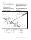
1
.
B
us
hi
ng
2. Ring-snap
3. Washer-thrust
4. Gear
5. Washer-thrust
6. Bearing-thrust
7
.
W
as
h
er-
th
rus
t
8. Bushing-input
9. Ring-quad
10. Key-woodruff
11. Shaft-impeller
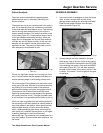
1
.
I
mpe
ll
er s
h
a
ft
2. Seal-oil
3. Bushing-input
4
.
B
us
hi
ng-
th
rus
t
5. Bearing-thrust
6. Ring-snap