


Belts, Controls and Linkages
2 - 6 Two Stage Snowthrower Drive Systems Manual
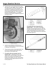
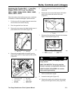
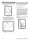
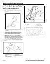
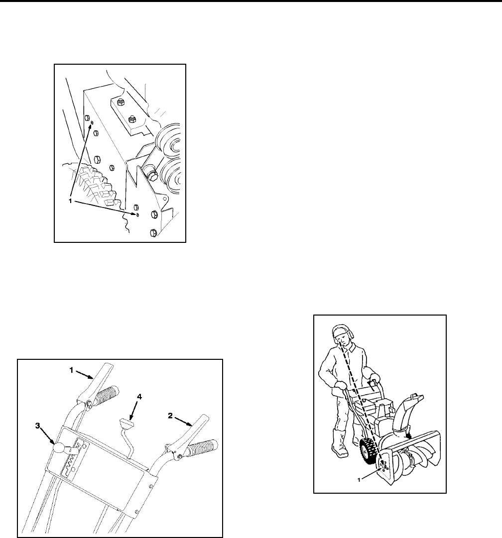
15. Reinstall (2) screws that secure auger brake arm
assembly. Make sure tabs fit into holes in left side
of machine (Figure 48).
Figure 48
M-2678
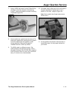
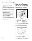
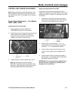
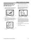
16. While someone squeezes the auger/impeller
control lever (Figure 49) against the handgrip,
reinstall belt guide using (2) screws, (2) washers,
and (2) lock washers removed previously. Check
and readjust belt guide, making sure it does not
contact any part of the engine pulley.
Figure 49
M-4035
17. Check and adjust auger drive linkage. Refer to
steps 5–7 of "Auger/Impeller Drive Control
Linkage — All Other Models" on page 2 - 8.
18. Reinstall idler pulley spring.
19. Reinstall belt cover with (3) screws.
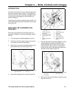
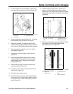
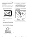
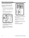
20. Make sure that auger and impeller are not rotating
when auger/impeller control lever is disengaged.
While standing in the operator position behind the
handles, look around to the side of the auger
housing. If the auger and impeller are rotating, a
large screw head on the side of the auger housing
will be rotating (Figure 50). If the auger and
impeller are rotating when the engine is
running and the auger/impeller control lever is
not engaged, immediately stop the unit. Refer
to "Adjusting Auger/Impeller Drive Belt" on
page 2 - 7.
IMPORTANT: Do not operate unit if auger and
impeller rotate when auger/impeller control lever
is not engaged.
Figure 50
M-2680
1
.
T
a
b
s
i
n
h
o
l
es
1
.
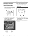
A
uger
/i
mpe
ll
er
control lever
2. Traction control lever
3
.
S
pee
d
se
l
ec
t
or
4. Discharge chute
control
1
.
L
arge screw
h
ea
d