


Belts, Controls and Linkages
2 - 2 Two Stage Snowthrower Drive Systems Manual
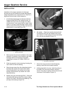
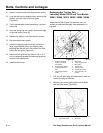
7. The belt guide must be checked and adjusted.
With the engine off, engage both the auger and
traction controls. Adjust the belt guide so that
there is approximately 1/8 inch (.3 cm) clearance
between the belt guide and the belt.
Check auger belt adjustment. See “CONTROL AND
LINKAGE ADJUSTMENT” on page 2 - 7 for the linkage
adjustment procedures.
REPLACING THE TRACTION BELT
The models covered in this manual use three different
methods of tensioning the traction belt. As the
tensioning method affects the belt replacement
process, they are separated by model number.
Replacing the Traction Belt — Toro
Models 38065, 38080, 38085
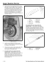
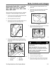
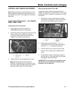
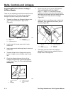
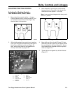
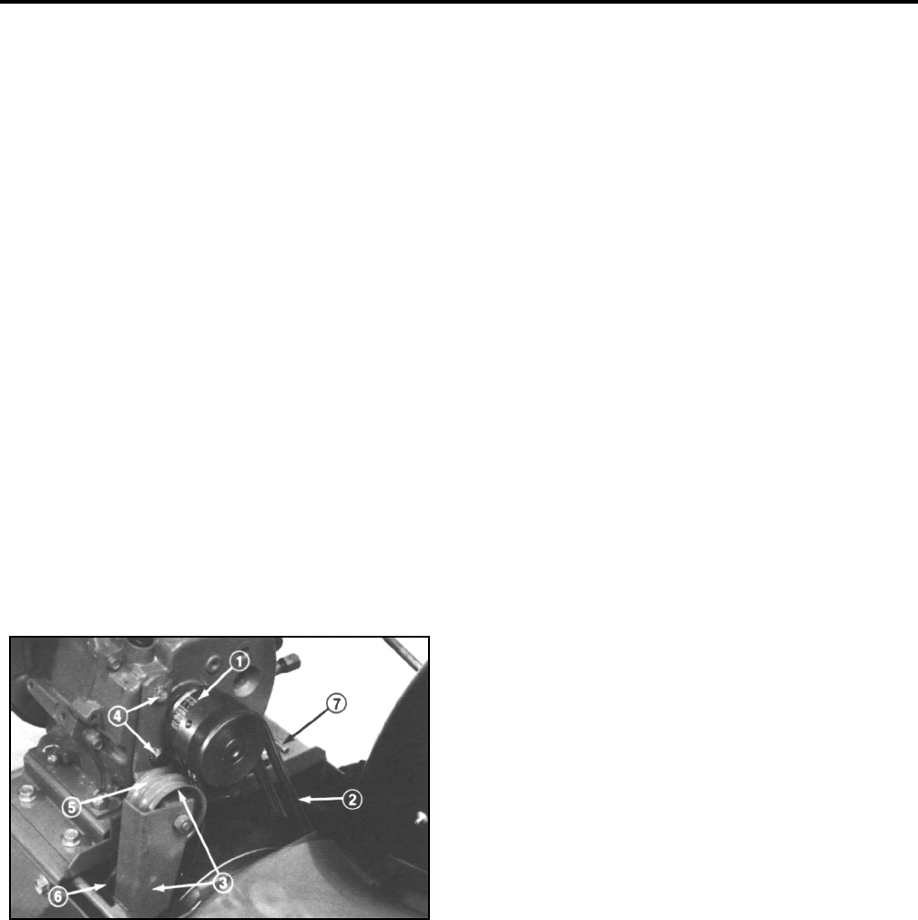
When traction drive belt (Figure 38) becomes worn,
stretched, oil-soaked, or otherwise damaged, replace
the belt.
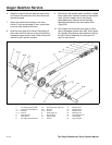
Figure 38
13299-32
1. Pull high tension wire off spark plug and make
sure it does not contact the plug accidentally.
2. Remove two thread forming screws holding belt
cover in place, and set belt guard aside.
3. Move auger drive control to DISENGAGE and
wheel drive control to N, neutral. Next, remove
auger drive belt from engine pulley and large
auger/impeller pulley.
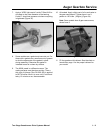
4. Loosen two capscrews (securing traction idler arm
to front of engine. Next, remove traction drive belt
from engine pulley and large traction pulley.
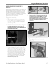
5. Install new belt around large traction pulley. Next,
loop belt over engine pulley, making sure that belt
is on inside of traction idler pulley and wire belt
guide.
6. Reinstall auger belt around large auger/impeller
pulley. Next, loop belt over engine pulley, making
sure that belt is on inside of auger/impeller, idler
pulley and wire belt retainer. Slide idler arm and
pulley assembly against belt to remove belt slack
and tighten capscrews.
Note: Tension belt only enough to remove slack.
Do not over-tension.
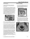
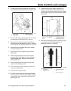
7. With the engine off, engage the auger lever.
Adjust the belt guide so it is within 1/8 inch (.3 cm)
of the belt.
8. Install belt cover with two thread forming screws.
9. Install high tension lead and test operate unit to
check traction. If little or no traction is evident,
proceed to step 10. If traction operation is
satisfactory, proceed to operate machine.
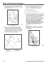
10. Remove high tension lead from spark plug and
remove belt guard. Loosen two capscrews
securing traction idler arm and slide idler arm and
pulley assembly further against belt. Move
assembly a minimal amount to assure belt is not
over tensioned.
1
.
T
rac
ti
on
d
r
i
ve
b
e
lt
2. Auger/impeller drive
belt
3. Auger/impeller pulley
and idler
4
.
C
apscrews,
t
rac
ti
on
idler
5. Traction idler pulley
6. Traction pulley
7. Belt guide