


Two Stage Snowthrower Drive Systems Manual 3 - 3
Traction Drive Systems
6. The axle can now be removed from the chassis.
Inspect the gear, the roll pin, and the areas where
the bearings contact the axle for damage or
severe wear. Remove the thrust washers from
either end of the axle. The purpose of the roll pin
and thrust washers is to limit the side to side
movement of the axle.
7. Disconnect the two clevis pins on the shift linkage
rods.
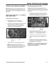
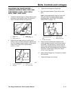
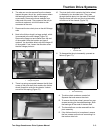
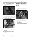
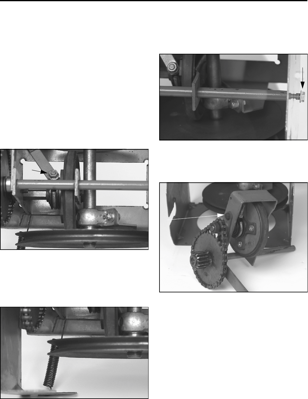
8. Next to the friction wheel is a large eyebolt, which
is connected to the shift linkage (Figure 74).
Remove the flange nut and washer from the end
of the eyebolt. Note the location and type of
washers. You should be able to slip the linkage off
of the eyebolt. If not, loosen the shoulder screw
that the linkage pivots on.
Figure 74
2768-32A
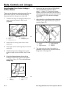
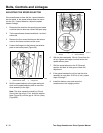
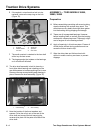
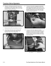
9. There is a spring connected between the left front
corner of the pivot shaft (that contains the friction
wheel) forward to a tab on the chassis. Unhook
one end of this spring (Figure 75).
Figure 75
2768-32B
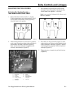
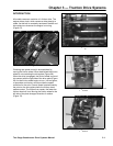
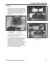
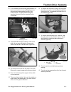
10. The pivot shaft, which contains the friction wheel,
is retained by two shoulder bolts. They pass
through the side plate, into the ends of the shaft.
Remove these two bolts and the pivot assembly
will slide out of the chassis (Figure 76).
Figure 76
2768-033
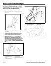
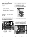
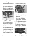
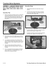
11. To disassemble the pivot assembly, proceed as
follows (Figure 77):
Figure 77
2768-036
A. The drive chain contains a master link.
Separate that and remove the chain.
B. To remove the friction wheel, remove four cap
screws securing the hex shaft bearings. Slide
the bearings off the ends of the hex shaft.
C. The hex shaft can now be removed from the
pivot assembly.
D. If the friction wheel is to be replaced, remove
the four screws and lock nuts connecting it to
the traction drive hub.
1
1
.
Fl
ange nu
t/
eye
b
o
lt
1
1
.
Sh
ou
ld
er
b
o
lt
1
1
.
H
ex s
h
a
ft
b
ear
i
ng