


Two Stage Snowthrower Drive Systems Manual 2 - 5
Belts, Controls and Linkages
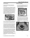
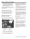
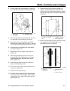
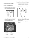
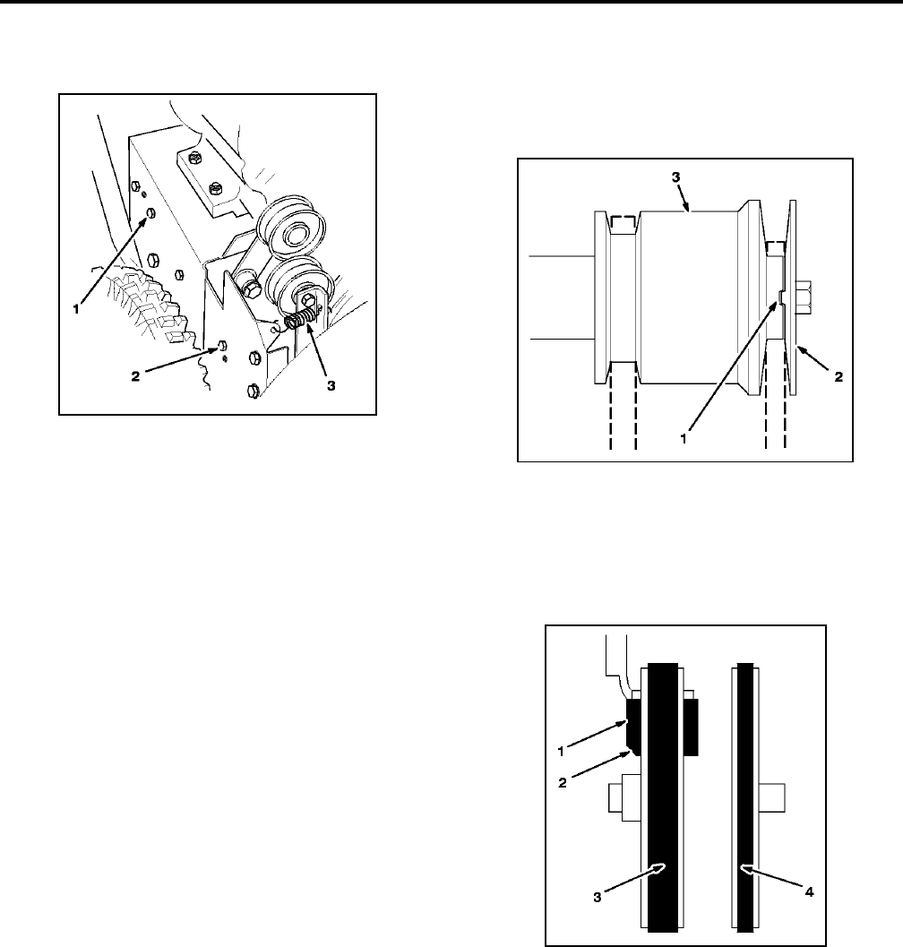
3. Loosen auger brake arm assembly by loosening
rear screw and removing front screw (Figure 45).
Figure 45
M-2678
4. Remove idler pulley spring (Figure 45). Let brake
arm assembly hang free but out of the way.
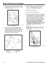
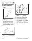
5. Remove (2) screws, (2) washers, and (2) lock
washers securing belt guide (Figure 43). If the belt
will not slip off, the engine pulley can be removed.
6. Remove engine crankshaft screw, lock washer
and washer (Figure 43).
7. Separate and remove engine pulley sheaves
(Figure 43).
8. Remove auger/impeller drive belt from center
engine pulley, leaving belt looped around large
auger/impeller pulley. Remove center engine
pulley (Figure 43).
9. Remove traction belt from traction pulley and
engine crankshaft (Figure 43).
10. Pull traction idler pulley outward and install new
traction belt (Figure 43).
11. Reinstall center engine pulley.
12. Pull idler pulley outward and loop auger/impeller
drive belt in front of center engine pulley, making
sure that belt is on inside of idler pulley and belt
guide (Figure 43).
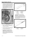
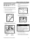
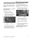
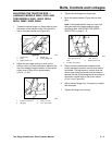
13. Reinstall engine pulley sheave, washer, lock
washer, and crankshaft screw. Make sure the
indexing rib in the engine pulley sheave is aligned
with the indexing notch in the center engine pulley
(Figure 46).
Figure 46
M-2677
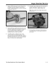
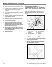
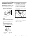
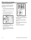
14. Make sure brake pad is properly installed on brake
arm. Angled cut-off on brake pad must be
positioned as shown in Figure 47.
Figure 47
M-2681
1
.
R
ear screw
2. Front screw
3
.
Idl
er pu
ll
ey spr
i
ng
1
.
I
n
d
ex
i
ng r
ib
i
n
i
n
d
ex
i
ng
notch
2
.
E
ng
i
ne pu
ll
ey s
h
eave
3. Center engine pulley
Vi
ew
f
rom
l
e
ft
s
id
e o
f
un
it
1. Brake pad
2. Angled cut-off
3. Auger/impeller drive
belt
4. Traction drive belt