


MV/
PUMP
12 3 4 5 67 8 9101112
MV/
PUMP
12 3 4 5 67 8 9101112
VC/
COM
VC/
COM
13141516171819202122 2324
VC/
COM
37383940414243444546 4748
37383940414243444546 4748
25262728293031323334 3536
25262728293031323334 3536
VC/
COM
VC/
COM
VC/
COM
VC/
COM
13141516171819202122 2324
VC/
COM
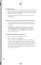
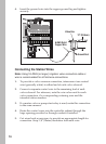
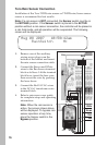
Connecting the Station Wires
74
1. To provide a valve common connection, interconnect one control
wire (generally white) to either lead of each valve solenoid.
2. Connect a separate control wire to the remaining lead of each
valve solenoid. For reference, note the wire color used for each
valve connection, it’s corresponding watering zone and the
intended station number.
3. If a master valve or pump start relay is used, make this connection
in the same manner.
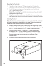
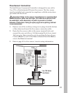
4. Route the control wires into the controller cabinet through the
large opening provided or through conduit if installed.
5. Cut wires back as necessary to provide an appropriate length for
connection. Strip 3/8”(10mm) insulation from each wire.
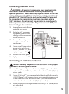
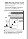
4. Insert the ground wire into the copper ground lug and tighten
securely.
Ground Rod
12" (30.5cm)
Valve Box
6 AWG Solid
Copper Wire
Note: Using 18 AWG (or larger) irrigation valve connection cable or
wire is recommended for all field wire connections.