


21
Dozer & Hitch Removal
DOZER & HITCH REMOVAL
NOTE: Connect male and female quick connectors to
prevent dirt and water from entering the hoses.
NOTE: Cross-over tubes must remain installed on the
tractor
1. Fully lower the attachment lift.
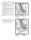
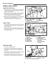
2. Disconnect the 1/2” (small) dozer hoses (D, Figure
35) from the 1/2” control valve hoses (C).
3. Connect the dozer hoses’ (D, Figure 35) male and
female quick connectors together. Also connect the
1/2” control valve hoses (C) to each other.
4. Disconnect the 23/32” (large) hoses (B, Figure 35)
from the cross-over tubes (A).
5. Connect the 23/32” hoses (B) to each other.
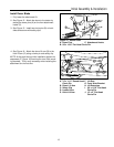
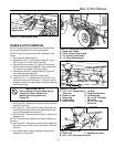
6. Install the 1/2” x 11” bypass hose (Figure 34) in the
cross-over tube quick connectors. You may need to
spread the cross-over tubes apart to keep the bypass
hose from kinking.
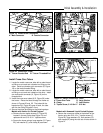
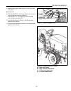
7. See Figure 36. Disconnect the dozer lift arm (B) from
the hitch lift arm (E).
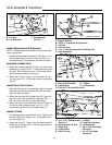
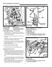
8. See Figure 37. Remove the 4 safety clips and clevis
pins (B) securing the dozer to the tractor and lift the
dozer off the attachment hooks (C).
9. See Figure 36. Disconnect the lift rod (F) from the lift
extension (H).
NOTE: The control arm support can remain attached to
the hitch.
10. See Figure 36. Remove the clevis pins (A) attaching
the front and rear of the hitch to the tractor. Remove
the hitch.
11. If the mower deck is being installed, remove the lift
extension (H, Figure 36).
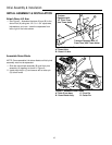
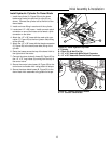
Figure 37. Attach Dozer
A. Dozer Pins C. Attachment Hooks
B. 5/8 x 1-5/8” Flat Head Clevis Pin
A
B
C
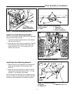
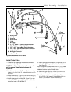
Figure 36. Lift Rod
A. 1/2 x 1-1/2” Round Head F. Lift Rod
Clevis Pin G. Front Hitch Bracket
B. Dozer Lift Arm H. Lift Extension
C. Safety Clip I. 5/8 x 1-5/8” Flat Head
D. Ladder Hitch Clevis Pin
E. Hitch Lift Arm J. 1/2 x 2” Flat Head
Clevis Pin
I
C
D
E
F
G
H
B
J
A
C
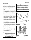
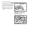
Figure 35. Disconnect Hydraulic Hoses
A. Cross Over Tubes
B. 23/32” Control Valve Hoses
C. 1/2” Control Valve Hoses
D. 1/2” Dozer Blade Hoses
A
B
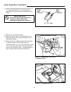
Figure 34. Install Bypass Hose
Do Not Kink
Bypass Hose
IMPORTANT NOTE
After removing the dozer blade, do not
operate the tractor without first
installing the the bypass hose
(Figure 34).
D
C