


18
Initial Assemble & Installation
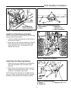
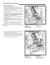
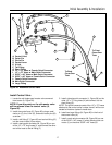
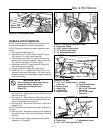
Figure 28. Cross-Over Tubes
A. Front Cross-Over Tube B. Back Cross-Over Tube
B
A
To Dozer
Hoses
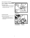
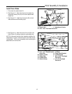
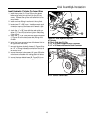
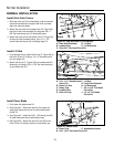
Figure 27. Control Valve
A. Control Valve
B. 23/32” x 40” Hose w/ Male Quick Connector
C. 23/32” x 40”Hose w/ Female Quick Connector
D. Support Arm
E. 1/4-20 x 1-3/4” Taptite Screws
A
D
C
B
To Front Cross-
Over Tube
To Back Cross-
Over Tube
E
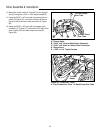
8. Mount the control valve (A, Figure 27) to the support
arm (D) using two 1/4-20 x 1-3/4” taptite screws (E).
9. Using the 23/32” x 40” hose with the male quick con-
nector (B, Figure 27), connect the IN port of the con-
trol valve (A) to the front cross-over tube (A, Figure
28).
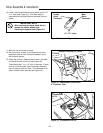
10. Using the 23/32” x 40” hose with the female quick
connector (C, Figure 27), connect the OUT port of the
control valve (A) to the back cross-over tube (B,
Figure 28).