


16
Initial Assemble & Installation
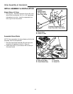
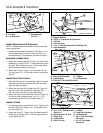
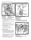
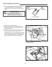
Install Bypass Hose & T-Connector
1. Install the 23/32” x 17” bypass hose (A, Figure 23)
from the power beyond port of the master valve to the
front cross-over tube (E).
2. Cut the return hose (B, Figure 23) 3” from the valve
as shown.
3. Install the T-connector (C, Figure 23) in the return
hose (B) and secure with hose clamps.
4. Connect the third leg of the T-connector (C, Figure
23) to the back cross-over tube (F) using the 5/8” x 9”
hose and hose clamps.
5. Tighten all fittings and hose clamps.
6. Run the tractor and check for leaks.
7. Reinstall the foam and lower dashboard screen.
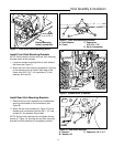
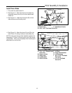
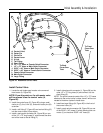
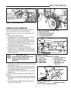
Assemble Control Arm
1. Assemble one clamp plate (C, Figure 24) below the
ladder hitch and one clamp plate (C) and lower con-
trol arm (E) above the hitch. Secure using two 1/2-13
x 5-1/2 capscrews, lockwashers, and nuts (F) and
one 1/2-13 x 3-1/2 capscrew, lockwasher, and nut
(G).
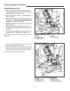
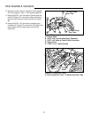
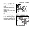
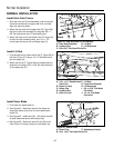
The clamp plate assembly (A, Figure 25) should be
approximately 7” behind the hitch mounting brackets
(D) as shown in Figure 25.
2. Insert the upper control arm (A, Figure 24) into the
lower control arm (E) and control valve plate (D).
Secure with 5/16-18 x 3/4” capscrews (B).
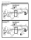
OUT
OUT
OUT
IN
IN
IN
BYD
BYD
BYD
O
O
O
Figure 23. Install T-Connector
A. Bypass Hose D.Hose Clamp
B. Return Hose E. Front Cross Over Tube
C. T-Connector F. Back Cross Over Tube
B
C
A
D
D
D
F
E
Figure 24. Assemble Upper Control Arm
A. Upper Control Arm
B. 5/16-18 x 3/4” Capscrew
C. Clamp Plate
D. Control Valve Plate
E. Lower Control Arm
F. 1/2-13 x 5-1/2 Capscrews, Lockwasher, & Nuts
G. 1/2-13 x 3-1/2 Capscrew, Lockwasher, & Nut
Mount Above
Ladder Hitch
Mount Below
Ladder Hitch
A
D
G
E
B
B
C
F
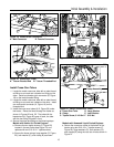
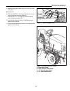
Figure 25. Attach Lower Control Arm Support
A. Clamp Plate
B. Lower Control Arm
C. 1/2-13 x 3-1/2” Capscrew, Lockwasher, & Nut
D. Hitch Mounting Bracket
B
C
D
A
Viewed From Right Side