


17
Initial Assembly & Installation
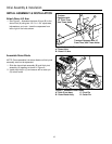
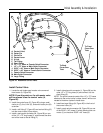
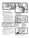
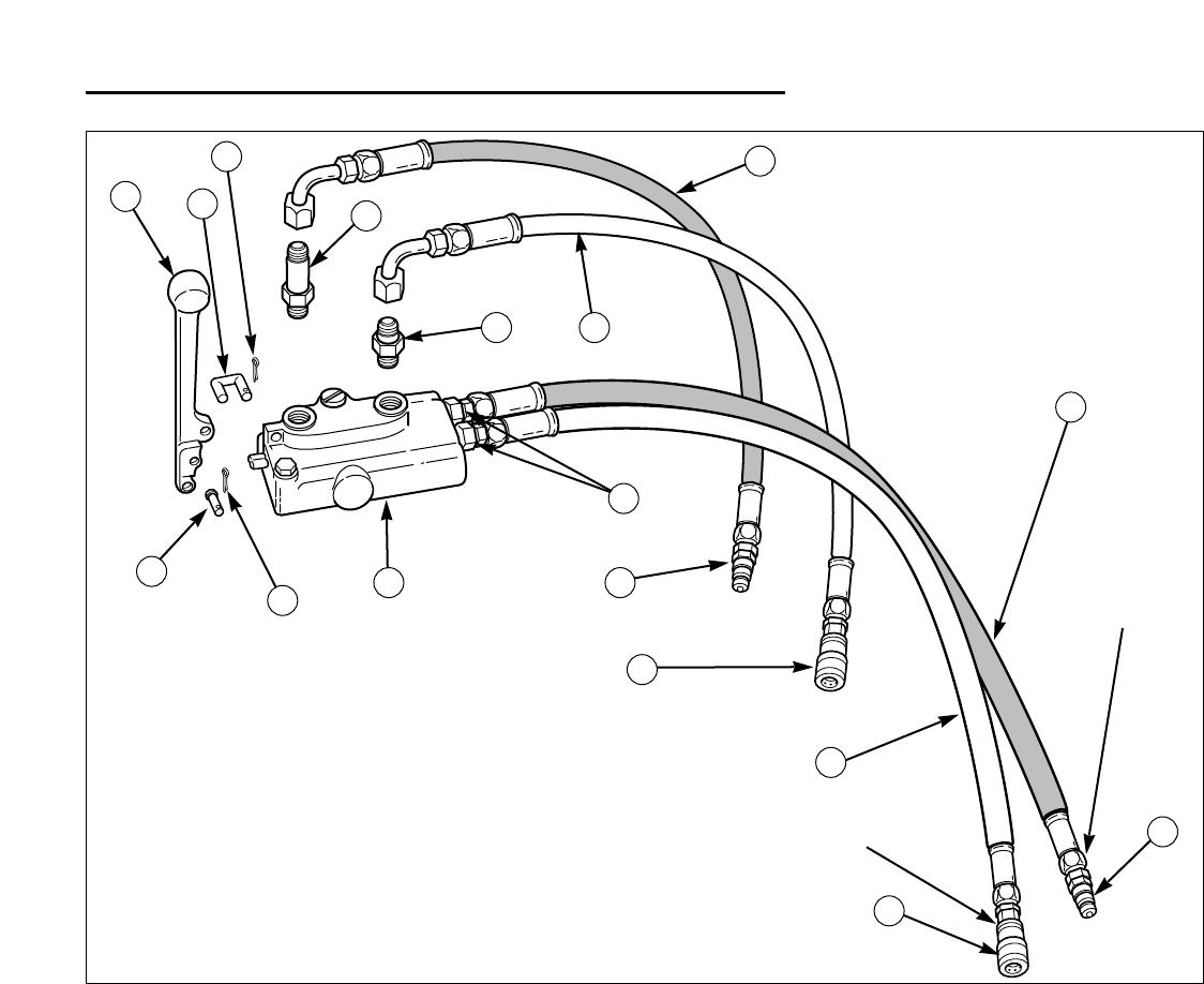
Install Control Valve
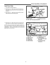
1. Locate the old single spool master valve removed
from tractor (A, Figure 26).
NOTE: From this point on, the old master valve
will be referred to as the control valve (A,
Figure 26).
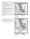
2. Install the control lever (D, Figure 26) using a small
clevis pin (C), the U-link (E), and small cotter pins (B)
as shown.
3. Install a tall fitting (F, Figure 26) and a short fitting (G)
into the control valve (A) as shown.
4. Install a male quick connector (M, Figure 26) on one
of the 1/2” x 75” long hoses (I), and connect the other
end of the hose to the tall fitting (F)
A. Control Valve
B. Cotter Pin
C. Clevis Pin
D. Control Lever
E. U-Link
F. Tall Fitting
G. Short Fitting
H. 1/2” x 75” Hose w/ Female Quick Connector
I. 1/2” x 75” Hose w/ Male Quick Connector
J. 23/32” x 40” Hose w/ Male Quick Connector
K. 23/32” x 40” Hose w/ Female Quick Connector
L. Female Quick Connector
M. Male Quick Connector
N. Large Fitting
D
E
B
B
C
A
F
I
G H
M
M
L
L
J
K
Figure 26. Assemble Control Valve
N
To Front
Cross-Over
Tube
To Back
Cross-Over
Tube
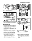
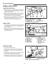
5. Install a female quick connector (L, Figure 26) on the
other 1/2” x 75” long hose (H) and connect it to the
short fitting (G).
NOTE: The quick connector ends of the 1/2” x 75” hoses
attached to the control valve in steps 4 and 5 will be con-
nected to the dozer hydraulic hoses later.
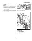
6. Install two large fittings (N, Figure 26) in the front of
the control valve (A).
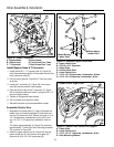
7. Install a male quick connector (M, Figure 26) on one
of the 23/32” x 40” hoses (J) and a female quick con-
nector (L) on the other 23/32” x 40” hose (K).