


12-3
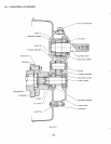
DISASSEMBLY and REASSEMBLY
of
1/2
REDUCER
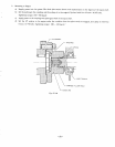
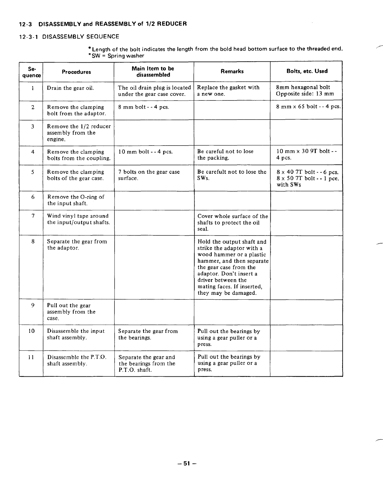
12-3-1
DISASSEMBLY
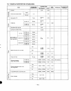
SEQUENCE
Length
of
the
bolt
indicates the length from the bold head bottom surface
to
the threaded end.
*SW
=
Spring washer
Procedures
Main Item to be
disassembled
Se-
quence
1
2
Remarks
Bolts,
etc. Used
Replace the gasket with
a new one.
8mm
hexagonal bolt
Opposite side:
13
mm
Drain the gear
oil.
The oil drain plug
is
located
under the gear case cover.
Remove the clamping
bolt from the adaptor.
~~ ~~
8
mm bolt
- -
4
pcs.
I
8
mm
x
65
bolt
--
4
pcs.
3
Remove the 1/2 reducer
assembly from the
engine.
Remove the clamping
10
mm bolt
- -
4
pcs.
bolts from the coupling.
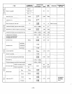
Remove the clamping
7
bolts on the gear case
bolts
of
the gear case.
surface.
Remove the O-ring
of
the input shaft.
4
Be careful not
to
lose
8
x
40
7T
bolt
-
-
6 pcs.
Be carefult not
to
lose the
4
pcs.
the packing.
10 mm
x
30
9T
bolt
--
sws.
8
x
50
7T
bolt
-
-
1
pce.
with
SWs
7
Wind vinyl tape around
the input/output shafts.
Cover whole surface
of
the
shafts to protect the
oil
seal.
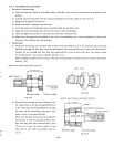
8
Separate the gear from
the adaptor.
Hold the output shaft and
strike the adaptor with a
wood hammer
or
a plastic
hammer, and then separate
the gear case from the
adaptor. Don't insert a
driver between the
mating faces.
If
inserted,
they may be damaged.
I
"
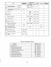
Pull out the gear
assembly from the
case.
Disassemble the input Separate the gear from
shaft assembly.
the bearings.
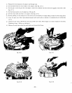
9
10
Pull out the bearings by
using a gear puller or a
press.
Disassemble the
P.T.O.
shaft assembly.
Separate the gear and
the bearings from the
P.T.O. shaft.
Pull out the bearings by
using a gear puller
or
a
press.
11
I
-
51
-