


CONTENTS
.
.
See
ti0
1
.
2
.
3
.
4
.
5
.
6
.
7
.
8
.
9
.
10
.
11
.
12
.
n
Ti
rle
Page
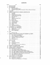
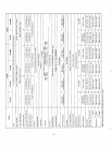
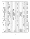
SPECIFICATIONS
.............................................
1
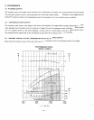
PERFORMANCE
..............................................
3
2-1 Maximum Output
.........................................
3
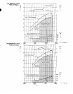
2-2 Continuous Rated Output
...................................
3
2-3 Maximum Torque and Fuel Consumption Ratio
at
Maximum Output
.......
3
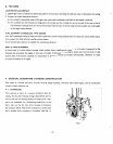
FEATURES
.................................................
5
GENERAL DESCRIPTION
of
ENGINE CONSTRUCTION
..................
5
4-
1
Crankcase
.............................................. 5
4-2 Crankshaft
.............................................
6
4-4 Cylinder and Cylinder Head
..................................
6
4-5 Gear Case Cover
..........................................
7
4-6 Camshaft
..............................................
7
4-8 Rocker Arm
............................................
7
4-9 Rocker Cover
............................................
8
4-10 Governor System
.........................................
8
4-1
1
Lubrication System
........................................
8
4- 13 Injection Pump
..........................................
9
4-14 Nozzle
................................................
9
4-
15 Combustion System
.......................................
10
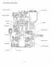
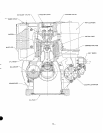
4- 16 Sectional View of Engine
....................................
11
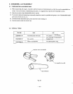
DISASSEMBLY
and
REASSEMBLY
.................
!
...............
13
5-2 Special
Tools
............................................
13
5-3 Disassembly Sequence
......................................
14
5-4 How to Reassemble
........................................
20
FUEL
......................................................
28
6-1
Qualityof Fuel
..........................................
28
GENERAL DESCRIPTION
of
AUXILIARY GADGETS
and
PARTS
...........
29
7
.
1 Fuel Injection
Pump
Mechanism
...............................
29
7-2
Fuel Injection Nozzle Holder
.................................
33
7-3 Governor Mechanism and Operation
.............................
36
7-4 Lubrication System and
Oil
Pump
..............................
38
7-5 Oil Filter
...............................................
38
7-6 Electric Apparatus
........................................
39
INSTALLATION
..............................................
40
8-1 Installing
...............................................
40
8-2
Ventilation
.............................................
40
8-3 Exhaust Gas Discharge
......................................
40
8-4
Fuel System
............................................
40
8-5
Power Transmission to Driven Machines
..........................
40
CHECKS
and
CORRECTIONS
.....................................
41
TABLE
of
CORRECTION STANDARDS
..............................
42
MAINTENANCE
and
STORING
....................................
45
11
-1
Daily Checks and Maintenance
.................................
45
11
-2
Every
25
Hours Checks and Maintenance
.........................
45
11
-3
Every
50
Hours
(10
days) Checks and Maintenance
...................
45
11 -4 Every
100
-
200 Hours (Monthly) Checks and Maintenance
.............
45
11
-5
Every
500
-
600 Hours (Semiannual) Checks
and
Maintenance
...........
46
11
-6
Every
1000
Hours (Yearly) Checks and Maintenance
..................
46
11
-7 Every
1500
Hours (Overhauls)
................................
46
11
-8 Preparation for Long Abeyance
................................
46
REDUCTIONS
for
B TYPE ENGINES
................................
47
12-1 Configuration
of
1/2 Reducer
................................
:
48
12-2 Structure
of
1/2 Reducer
....................................
49
12-3 Disassembly and Reassembly
of
1/2 Reducer
.......................
51
4-3 Connecting Rod and Piston
..................................
6
4-7 Tappet and Tappet Guide
....................................
7
4- 12 Cooling System
..........................................
9
5-
1
Preparations and Suggestions
.................................
13