HD151TS207SS
Rev.1.00, Apr.25.2003, page 4 of 38
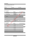
Pin Descriptions
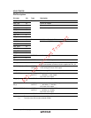
Pin name No. Type Description
VSS_A 54 Ground for PLL
VSS_CPU 45 Ground for outputs
VSS_IREF 53 Ground for current reference
VSS_SRC 39
VSS_3V66 25
VSS_PCI 11, 17
VSS_REF 6
VSS_48 33
Ground
Ground for outputs
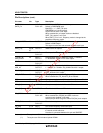
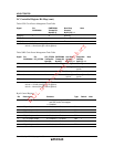
VDD_A 55 3.3 V Power Supply for PLL
VDD_CPU 42, 48
VDD_SRC 36
VDD_3V66 24
VDD_PCI 10, 16
VDD_REF 3
VDD_48 34
Power
3.3 V Power Supply for outputs
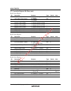
REF0 1
REF1 2
OUTPUT 3.3 V 14.318 MHz reference clock.
XTAL_IN 4 INPUT 14.318 MHz XTAL input.
XTAL_OUT 5 OUTPUT 14.318 MHz XTAL output.
Don’t connect when an external clock is applied at XTAL_IN.
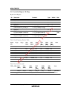
FS2/PCIF_[0:1] 7,8 INPUT/
OUTPUT
Frequency select latch input pin.
/Free running PCI clock 3.3 V output.
PCIF_2 9 OUTPUT Free running PCI clock 3.3 V output.
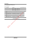
**MODE/PCI_0 12 INPUT/
OUTPUT
Function select latch input pin for pin 22,
1 = Reset#, 0 = clock output.
/PCI clock 3.3 V output.
PCI_[1:3] 13,14,
15
OUTPUT PCI clock 3.3 V outputs.
**SEL100_200/
PCI_4
18 INPUT/
OUTPUT
Latched select input for SRC output.
1 = 200 MHz, 0 = 100 MHz
/PCI clock 3.3 V output.
**SEL33_25/PCI_5 19 INPUT/
OUTPUT
Latched select input for PCI5 output.
1 = 25 MHz, 0 = 33 MHz
/PCI clock 3.3 V output.
PCI_6 20 OUTPUT PCI clock 3.3 V outputs.
Note: (*): Those pins are 150 kΩ internal pulled-UP.
(**): Those pins are 150 kΩ internal pulled-DOWN.


