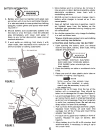
3.
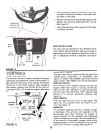
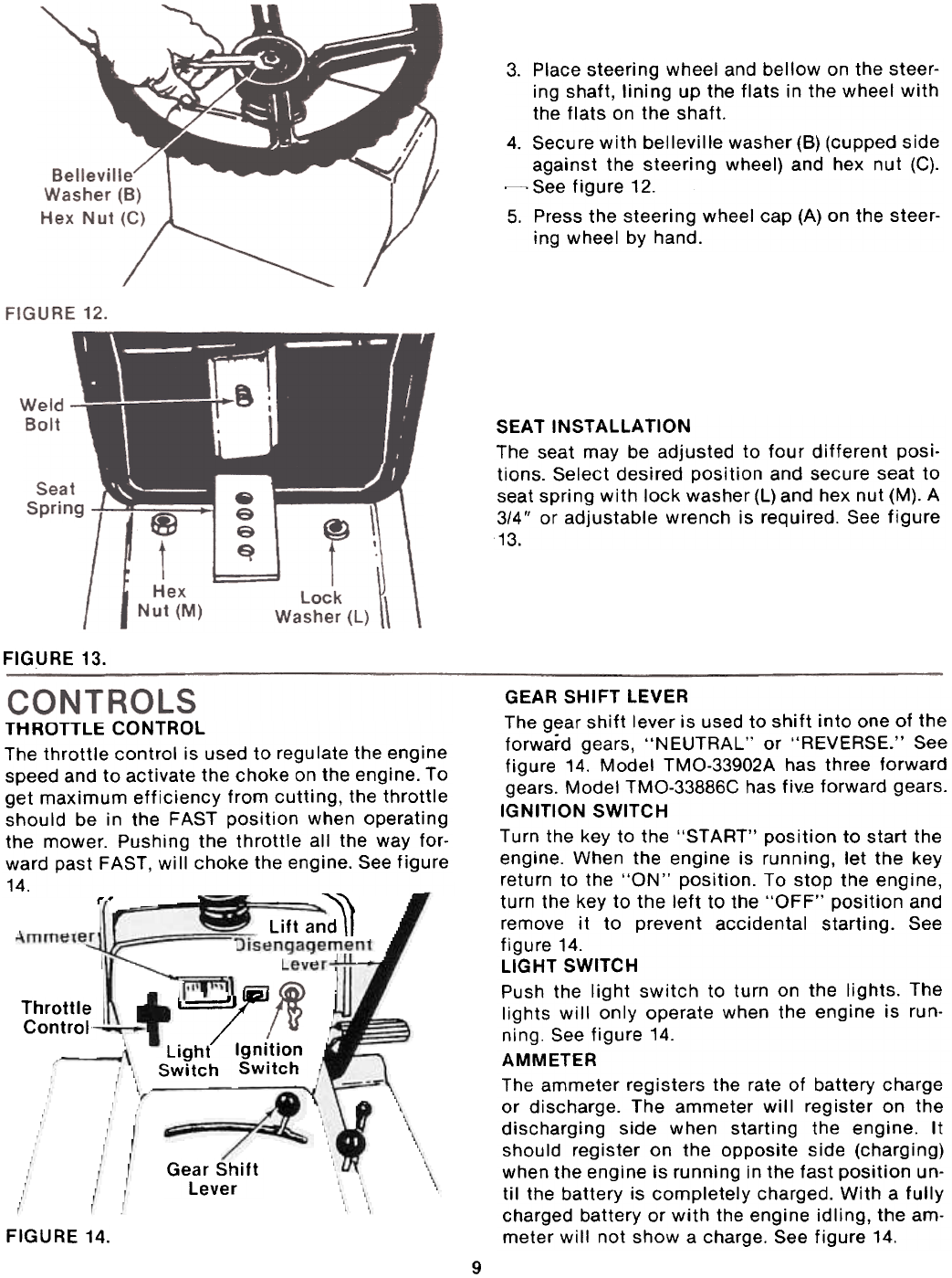
Place steering wheel and bellow on the steer-
ing shaft, lining up the flats in the wheel with
the flats on the shaft.4.
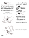
Secure with belleville washer (6) (cupped side
against the steering wheel) and hex nut (C).
~ See figure 12.
5. Press the steering wheel cap (A) on the steer-
ing wheel by hand.
SEAT INSTAllATION
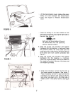
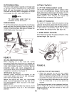
The seat may be adjusted to four different posi.
tions. Select desired position and secure seat to
seat spring with lock washer (l) and hex nut (M). A
3/4" or adjustable wrench is required. See figure
13.
FIGURE 13.
Lift an~
t'~
k..==!J/:,
Light Ignition
Switch Switch
Throttle
Control~
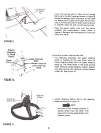
GEAR SHIFT LEVER
The gear shift lever is used to shift into one of the
forward gears, "NEUTRAL" or "REVERSE." See
figure 14. Model TMO-33902A has three forward
gears. Model TMO-33886C has fivE forward gears.
IGNITION SWITCH
Turn the key to the "START" position to start the
engine. When the engine is running, let the key
return to the "ON" position. To stop the engine,
turn the key to the left to the "OFF" position and
remove it to prevent accidental starting. See
figure 14.
LIGHT SWITCH
Push the light switch to turn on the lights. The
lights will only operate when the engine is run-
ning. See figure 14.
AMMETER
The ammeter registers the rate of battery charge
or discharge. The ammeter will register on the
discharging side when starting the engine. It
should register on the opposite side (charging)
when the engine is running in the fast position un-
til the battery is completely charged. With a fully
charged battery or with the engine idling, the am-
meter will not show a charge. See figure 14.
Gear Shift
Lever
FIGURE 14.
9
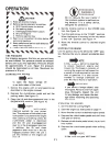
THROTTLE CONTROL
The throttle control is used to regu late the eng ine
speed and to activate the choke on the engine. To
get maximum efficiency from cutting, the throttle
should be in the FAST position when operating
the mower. Pushing the throttle all the way for-
ward past FAST, will choke the engine. See figure
14.
,-- ~


