


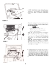
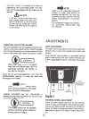
CUTTING CONTROLS
CLUTCH.BRAKE PEDALThe
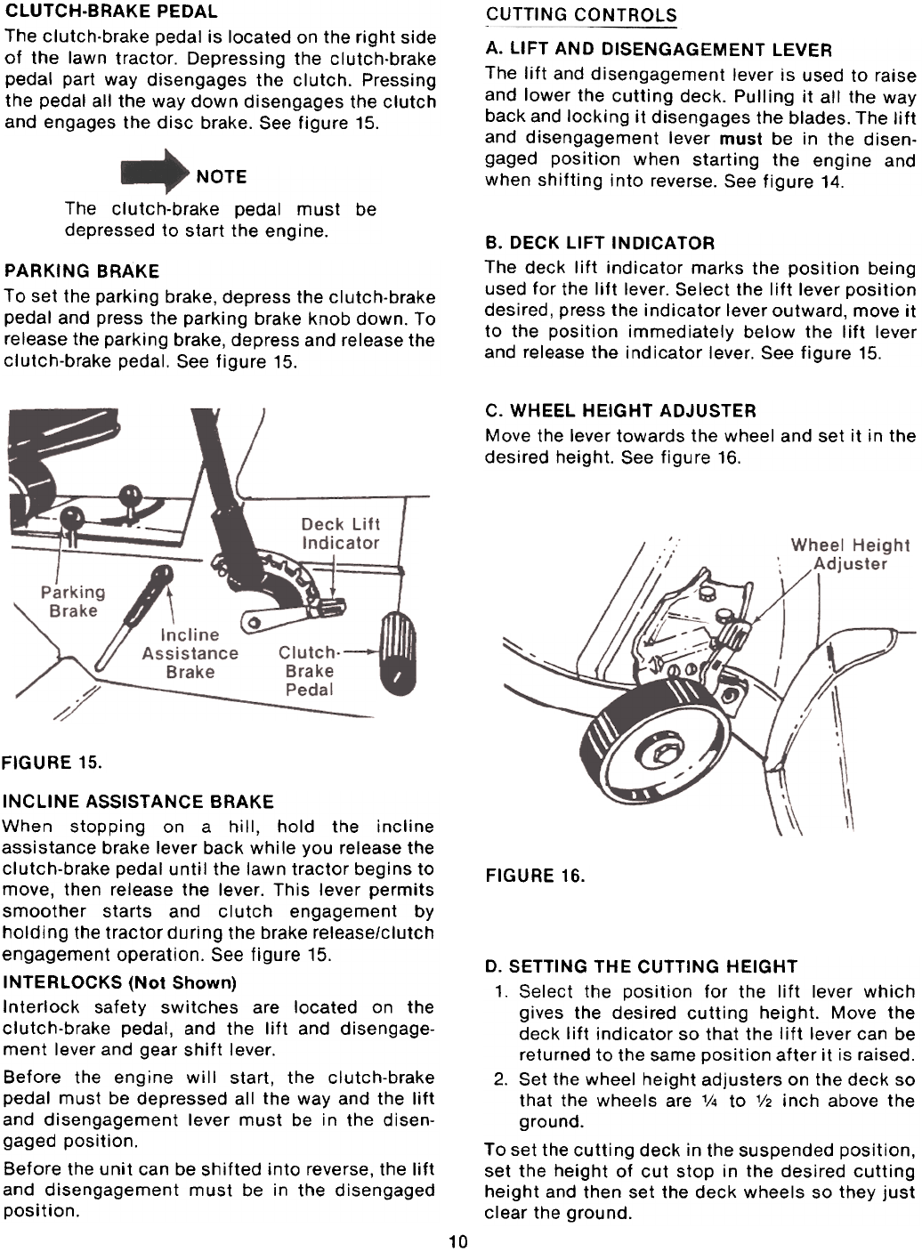
clutch-brake pedal is located on the right side
of the lawn tractor. Depressing the clutch-brake
pedal part way disengages the clutch. Pressing
the pedal all the way down disengages the clutch
and engages the disc brake. See figure 15.
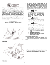
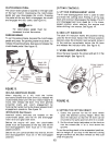
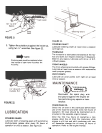
A. LIFT AND DISENGAGEMENT LEVER
The lift and disengagement lever is used to raise
and lower the cutting deck. Pulling it all the way
back and locking it disengages the blades. The lift
and disengagement lever must be in the disen-
gaged position when starting the engine and
when shifting into reverse. See figure 14.
NOTE
The clutch-brake pedal must be
depressed to start the engine.
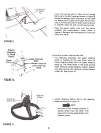
B. DECK LIFT INDICATOR
The deck lift indicator marks the position being
used for the lift lever. Select the lift lever positiondesired,
press the indicator lever outward, move it
to the position immediately below the lift lever
and release the indicator lever. See figure 15.
PARKING BRAKE
To set the parking brake, depress the clutch-brake
pedal and press the parking brake knob down. To
release the parking brake, depress and release the
clutch-brake pedal. See figure 15.
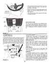
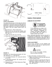
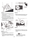
C. WHEEL HEIGHT ADJUSTER
Move the lever towards the wheel and set it in the
desired height. See figure 16.
FIGURE 15.
FIGURE 16.
D. SETTING THE CUTTING HEIGHT
1. Select the position for the lift lever which
gives the desired cutting height. Move the
deck lift indicator so that the lift lever can be
returned to the same position after it is raised.
2. Set the wheel height adjusters on the deck so
that the wheels are 1/4 to 1/2 inch above the
ground.To
set the cutting deck in the suspended position,
set the height of cut stop in the desired cutting
height and then set the deck wheels so they just
clear the ground.
INCLINE ASSISTANCE BRAKE
When stopping on a hill, hold the incline
assistance brake lever back while you release the
clutch-brake pedal until the lawn tractor begins to
move, then release the lever. This lever permits
smoother starts and clutch engagement by
holding the tractor during the brake release/clutch
engagement operation. See figure 15.
INTERLOCKS (Not Shown)
Interlock safety switches are located on the
clutch-brake pedal, and the lift and disengage-
ment lever and gear shift lever.
Before the engine will start, the clutch-brake
pedal must be depressed all the way and the lift
and disengagement lever must be in the disen-
gaged position.
Before the unit can be shifted into reverse, the lift
and disengagement must be in the disengaged
position.
10