3.
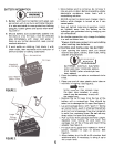
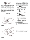
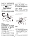
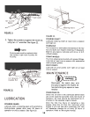
Lift the transmission cover. Unplug the green
safety wire from beneath the transmission-cover.
See figure 6. Remove transmission
cover.
FIGURE 6.
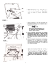
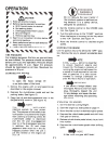
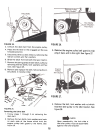
4. Place the battery in the lawn tractor so that
the positive terminal is facing the right side of-the
unit. See figure 7.
NOTE
Right and left hand sides of the unit
are determined from the operating
position, facing forward.
5.
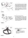
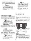
Slide the square nut (provided with battery
hardware) into the positive (+) terminal. Place
the positive (heavy red wire) cable and the
small red wire on the positive terminal. Secure
with screw and lock washer provided. See
figure 7.6.
Slide the square nut (provided with battery
hardware) into the negative (-) terminal.
Place the negative (heavy black wire) cable on
the negative terminal. Secure with screw and
lock washer provided.
FIGURE 7.
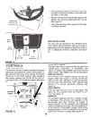
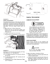
7. Hook one hold-down rod (G) into the hole in
the frame beside the battery. See figure 7.
Place the battery cover (F) in position over the
hold-down rod. Secure with wing nut (H). At-
tach other hold-down rod to the other side of
battery cover in the same manner. See figure-8.
7


