7.
The lawn tractor is brought to a stop by
depressing the clutch-brake pedal. The drive
belt will be disengaged and the brake will be
applied.
NOTE
~ CAUTION
If the unit is not to be used for a
long period, place the gear shift
lever in NEUTRAL, stop the engine,
set the parking break and remove
the key. DO NOT leave the machine
on an incline.
Under normal usage bag material is
subject to wear, and should be
checked periodically. Be sure any
replacement bag complies with the
mower manufacturer's recommen-daitons.
For replacement bags, use only fac-
tory authorized replacement bag
No. 764-0121.
OPERATING THE CUTTING BLADES
The cutting blades may be engaged while the lawn
tractor is moving or standing still. DO NOT engage
the cutting blades abruptly as the sudden belt ten-
sion on the pulley may cause the engine to stall.
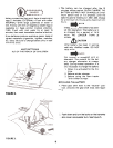
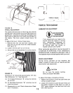
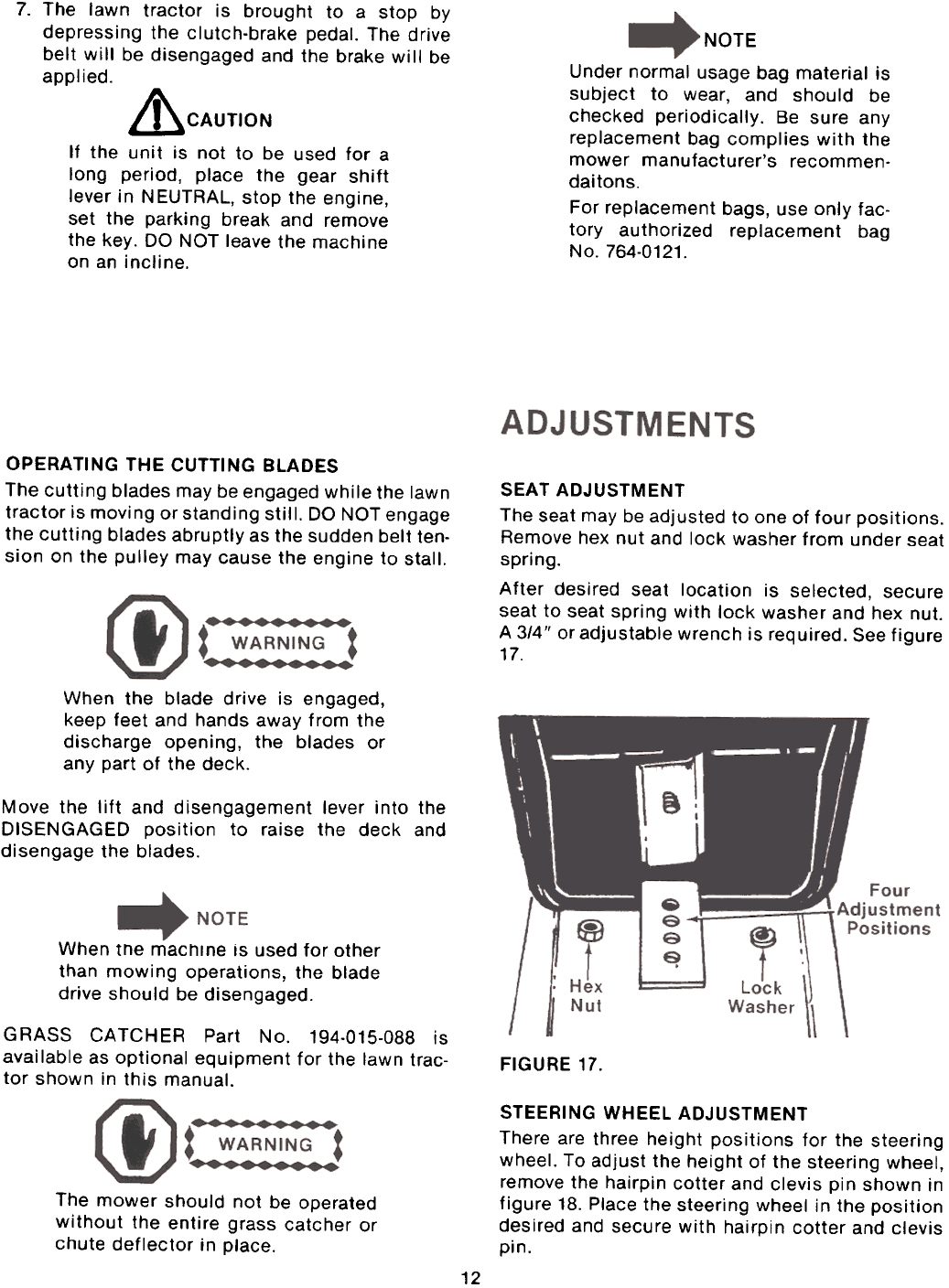
SEAT ADJUSTMENT
The seat may be adjusted to one of four positions.
Remove hex nut and lock washer from under seatspring.After
desired seat location is selected, secure
seat to seat spring with lock washer and hex nut.
A 3/4" or adjustable wrench is required. See figure
17.
When the blade drive is engaged,
keep feet and hands away from the
discharge opening, the blades or
any part of the deck.
Move the lift and disengagement lever into the
DISENGAGED position to raise the deck and
disengage the blades.
When the machine is used for other
than mowing operations, the blade
drive should be disengaged.
GRASS CATCHER Part No. 194-015-088 is
available as optional equipment for the lawn trac-
tor shown in this manual.
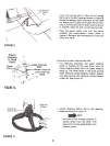
FIGURE 17.
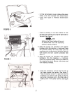
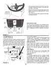
STEERING WHEEL ADJUSTMENTThere
are three height positions for the steeringwheel.
To adjust the height of the steering wheel,
remove the hairpin cotter and clevis pin shown in
figure 18. Place the steering wheel in the positiondesired
and secure with hairpin cotter and clevispin.
The mower should not be operated
without the entire grass catcher or
chute deflector in place.
12


