OPERA TION
Do not operate the lawn tractor if
the interlock system is malfunction-
ing because it is a safety device,
designed for protection.
4.
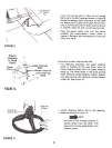
Set the throttle control in the CHOKE posi-
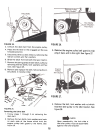
tion. See figure 14.5.
Turn the ignition key to the "START" position.
When the engine is running, let the key return
to the "ON" position. See figure 14.6.
Move the throttle control to desired engine
speed.
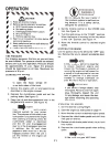
~ ~ CAUTION
~ 1. Keep all shields in place.
". 2. Before leaving operator's position:
~ a. Shift transmission to neutral
". b. Set parking brake
~ c. Disengage attachment clutch
". d. Shut off engine
~ e. Remove ignition key
". 3. Wait for all movement to stop before
~ servicing machine.
'" 4. Keep people and pets a safe distance
~ away from machine.
'" 5. Look to the rear before backing up.
STOPPING THE ENGINE
Turn the ignition key to the left to the "OFF" posi-
tion. Remove the key to prevent accidental start-
ing.
TIRE PRESSURE
For shipping purposes, the tires on your unit may
be over.inflated. Tire pressure should be reduced
before unit is put into operation. Pressure should
be approximately 15 p.s.i. Equal tire pressure
should be maintained on all tires. Maximum tire
pressure is 30 p.s.i.
STARTING THE ENGINE
NOTE
A brief break-in period is essential
to ensure maximum engine and
mower life. The break-in consists of
running the engine at half speed for
a period of time required to use one
tank of gasoline. It is also recom-
mended to change crankcase oil
after the first 5 hours of operation.
NOTE
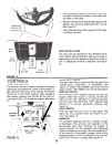
To open the hood, simply lift
up on both sides of the hood.
IMPORTANT
If you strike a foreign object, stop
the engine. Remove wire from sparkplug,
thoroughly inspect the unit
for any damage, and repair the dam-
age before restarting and operating
the mower.
1. Service the engine with oil and gasoline as
described in the engine manual.
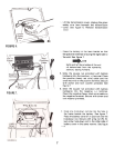
2. Depress the clutch-brake pedal and set the
parking brake. See figure 15.3.
Place the lift and disengagement lever in the
DISENGAGED position. See figure 15.
This unit is equipped with a safety
interlock system for your protec-
tion. The purpose of the safety inter-
lock system is to prevent the engine
from cranking or starting unless the
clutch-brake pedal is depressed
and the lift and disengagement
lever is in the disengaged position.
In addition, the lift and disen-
gagement lever must be in the dis-
engaged position when the unit is
put into reverse or the engine will
shut off.
OPERATING THE MOWER
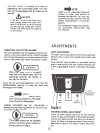
1. Set the desired cutting height.
2. Start the engine as instructed on page 11.
3. Move throttle control to desired engine speed.
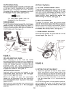
4. Depress the clutch-brake pedal and shift into
first gear or reverse.
5. Release clutch-brake pedal slowly to put unit
into motion.
6. Depress the clutch-brake pedal when shifting
gears.
Do not force the gear shift lever!
11


