


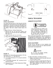
8.
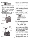
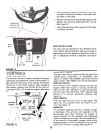
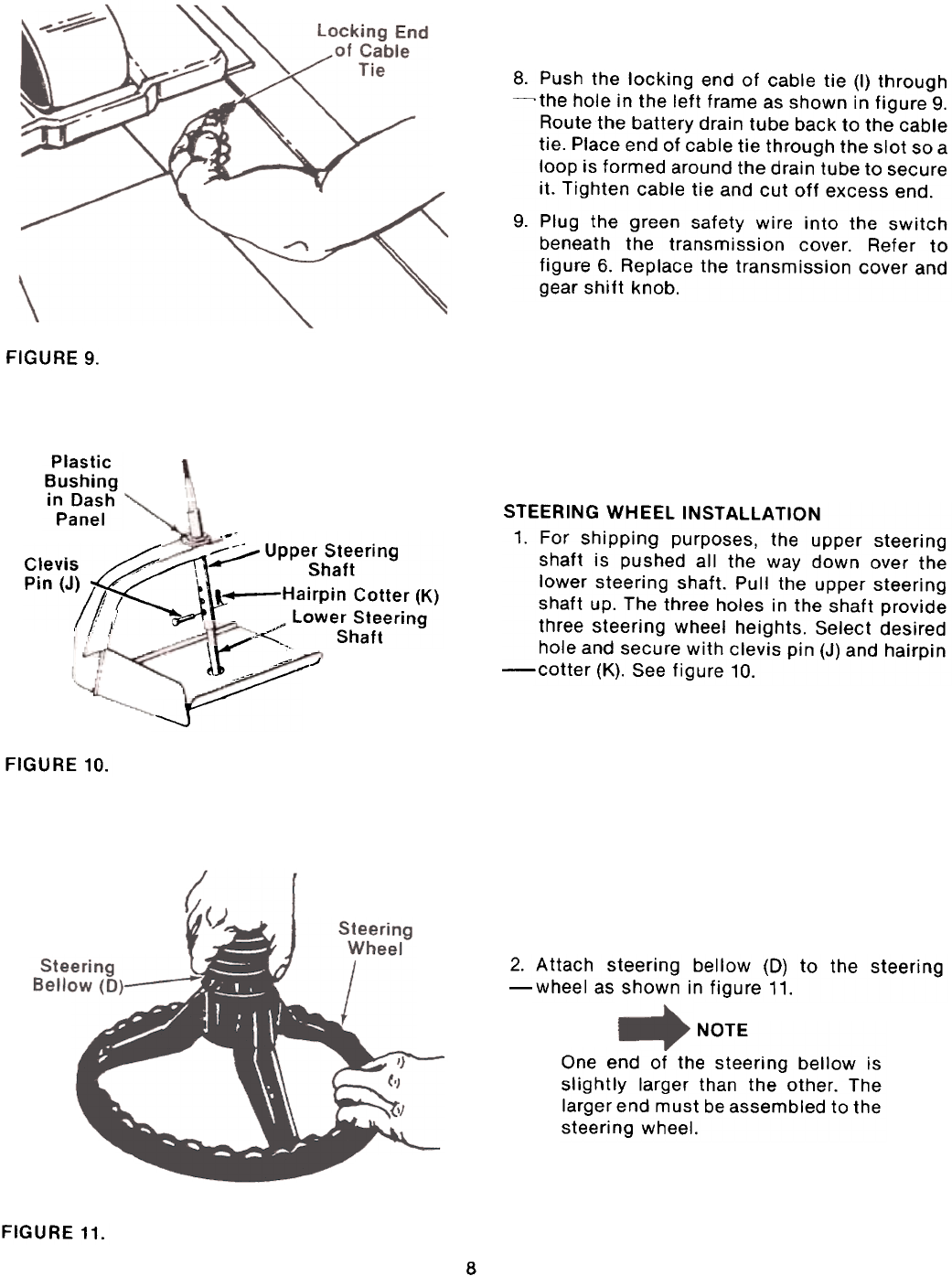
Push the locking end of cable tie (I) through~the
hole in the left frame as shown in figure 9.
Route 1he battery drain tube back to the cable
tie. Place end of cable tie through the slot so a
loop is formed around the drain tube to secure
it. Tighten cable tie and cut off excess end.9.
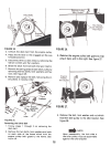
Plug the green safety wire into the switch
beneath the transmission cover. Refer to
figure 6. Replace the transmission cover and
gear shift knob.
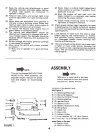
FIGURE 9.
Plastic
Bushing
in Dash
Panel
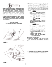
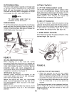
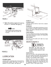
STEERING WHEEL INSTAllATION
1. For shipping purposes, the upper steering
shaft is pushed all the way down over the
lower steering shaft. Pull the upper steering
shaft up. The three holes in the shaft provide
three steering wheel heights. Select desired
hole and secure with clevis pin (J) and hairpin-cotter
(K). See figure 10.
._~
~ :;;;./ Upper Steering Clevis "' \ Shaft Pin (J)
~! -Hairpin Cotte: (K)
,: I -Lower Steering
, I ;..~~ Shaft
.,..-
lr-::"~
...t~
~J--~
FIGURE 10.
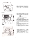
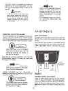
2. Attach steering bellow (D) to the steering-wheel
as shown in figure 11.
NOTE
One end of the steering bellow is
slightly larger than the other. The
larger end must be assembled to the
steering wheel.
FIGURE 11.
8