


J\
r---~
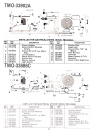
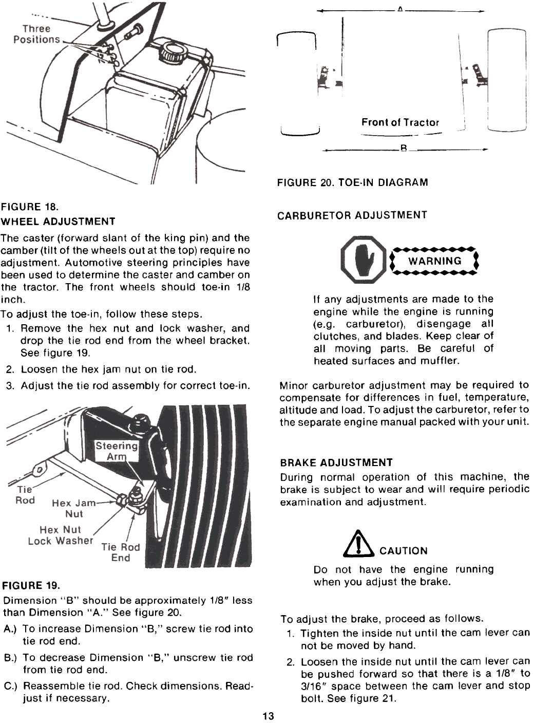
Front of Tractor
-----
L
J
R
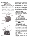
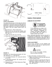
FIGURE 20. TOE-IN DIAGRAM
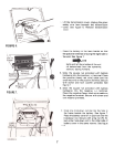
CARBURETOR ADJUSTMENT
',
~ WARNING t
'
If any adjustments are made to the
engine while the engine is running(e.g.
carburetor), disengage allclutches,
and blades. Keep clear of
all moving parts. Be careful of
heated surfaces and muffler.
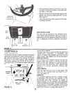
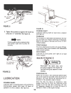
FIGURE 18.
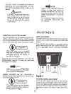
WHEEL ADJUSTMENTThe
caster (forward slant of the king pin) and the
camber (tilt of the wheels out at the top) require no
adjustment. Automotive steering principles have
been used to determine the caster and camber on
the tractor. The front wheels should toe.in 1/8
inch.To
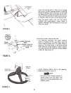
adjust the toe-in, follow these steps.
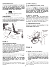
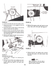
1. Remove the hex nut and lock washer, and
drop the tie rod end from the wheel bracket.
See figure 19.
2. Loosen the hex jam nut on tie rod.
3. Adjust the tie rod assembly for correct toe-in.
Minor carburetor adjustment may be required to
compensate for differences in fuel, temperature,
altitude and load. To adjust the carburetor, refer to
the separate engine manual packed with your unit.
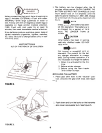
BRAKE ADJUSTMENT
During normal operation of this machine, the
brake is subject to wear and will require periodic
examination and adjustment.
& CAUTION
Do not have the engine running
when you adjust the brake.
To adjust the brake, proceed as follows.
1. Tighten the inside nut until the cam lever can
not be moved by hand.
2. Loosen the inside nut until the cam lever can
be pushed forward so that there is a 1/8" to
3/16" space between the cam lever and stop
bolt. See figure 21.
FIGURE 19.
Dimension "B" should be approximately 1/8" less
than Dimension "A." See figure 20.
A.) To increase Dimension "B," screw tie rod into
tie rod end.
B.) To decrease Dimension "B." unscrew tie rod
from tie rod end.
C.) Reassemble tie rod. Check dimensions. Read-
just if necessary.
13