


(2) Never make a cutting height adjustment
while engine is running if operator must
dismount to do so.
(3) Shut the engine off and wait until the
blade comes to a complete stop before
removing the grass catcher.
(4) Check blade mounting bolts for proper
tightness at frequent intervals.
34. Check grass catcher bags frequently for wear
or deterioration. For safety protection, replace
only with new bag meeting original equipment
specifications.35.
Look behind to make sure the area is clear
before placing the transmission in reverse
and continue looking behind while backing
up. Disengage blades before shifting into
reverse and backing up.
36. This unit should not be driven up a ramp onto
a trailer or truck under power, because the
unit could tip over, causing serious personal
injury. The unit must be pushed manually to
load properly.
27. Keep the vehicle and attachments in good
operating condition, and keep safety devices
in place. Use guards as instructed in
operator's manual.
28. Keep all nuts, bolts, and screws tight to be
sure the equipment is in safe working condi-
tion.
29. Never store the equipment with gasoline in
the tank inside a building where fumes may
reach an open flame or spark. Allow engine to
cool before storing in any enclosure.
30. To reduce fire hazard, keep engine free of
grass, leaves or excessive grease.
31. The vehicle and attachments should be
stopped and inspected for damage after strik-
ing a foreign object. The damage should be
repaired before restarting and operating the
equipment.
32. Do not change the engine governor settings
or overs peed the engine.33.
When using the vehicle with mower, proceed
as follows:
(1) Mow only in daylight or in good artificial
light.
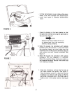
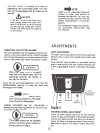
ASSEMBLY
NOTE
This unit is shipped WITHOUT GAS-
OLINE or OIL. After assembly, see
separate engine manual for proper
fuel and engine oil recommenda-
tions.
NOTE
Reference to right hand or left hand
side of machine is from the operat-
ing position, facing forward.
A_' ~ --J -fr
B--I;::;. K ~'
C-@ -f('
D--_~ ~ F
~r -.,~~ ~ r
H
E-')J
~;:~~ 1
~
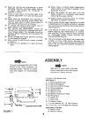
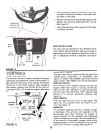
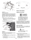
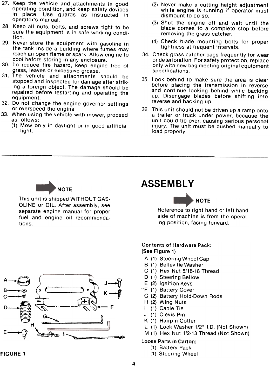
FIGURE 1.
Contents of Hardware Pack:
(See Figure 1)
A (1) Steering Wheel Cap
B (1) Belleville Washer
C (1) Hex Nut 5/16-18 Thread
0 (1) Steering Bellow
E (2) Ignition Keys
'F (1) Battery Cover
G (2) Battery Hold-Down Rods
H (2) Wing Nuts
I (1) Cable Tie
J (1) Clevis Pin
K (1) Hairpin Cotter
L (1) Lock Washer 1/2" 1.0. (Not Shown)
M (1) Hex Nut 1/2-13 Thread (Not Shown)
Loose Parts in Carton:
(1) Battery Pack
(1) Steeri ng Wheel
4