


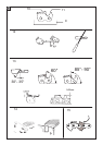
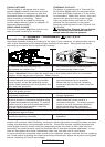

CHAIN CATCHER
This machine is equipped with a chain
catcher (fig.4) located under the sprocket.
This mechanism is designed to stop the
backward chain movement in the case of
chain breaking or derailing. These
situations can be avoided by ensuring
correct chain tension (Refer to chapter “D.
Assembly/disassembly”).
REAR HAND GUARD
This acts to protect (fig.5) the hand in the
case of chain breaking or derailing.
THERMAL CUT-OUT
The Motor is protected by a Thermal Cut-
Out Switch (fig 6) which is activated when
the chain becomes jammed or if the motor
is overloaded. When this occurs, stop and
remove the plug from the power supply,
clear any obstruction and wait for a few
minutes for the product to cool down.
Reset by pushing back in the Thermal Cut-
Out Switch.
Resetting the Thermal Cut-out Switch
with the chain brake released and the
switch held will start the product.
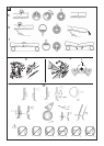
D. ASSEMBLY / DISASSEMBLY 2,3,6,7,8,9,12
BAR AND CHAIN ASSEMBLY
Assembly methods change according to the type of your machine- so please take care to
refer to the illustrations and machine type marked on the label. Take great care when
assembling to ensure this is performed correctly.
1. Check that the chain brake is not activated. If so, deactivate it.
2a. Unscrew the bar retaining nut 2b. Unscrew the bar retaining knob
and remove the chain cover. and remove the chain cover.
3 Position the chain over the bar, starting at the nose sprocket, fitting into the bar guide
groove. Attention! Ensure that the sharp side of the cutting teeth face in a frontward
direction on the upper part of the bar. Wear Gloves.
4a. Ensure the chain tensioner pin is as 4b. Rotate the metal scroll wheel
far back towards the sprocket as possible, anti-clockwiseas far as possible.
Mount the bar on the bar retaining screw Mount the bar on the bar retaining
and the chain tensioner pin and position the screw and position the chain over the
chain over the sprocket sprocket.
Replace the chain cover, ensuring the drive teeth of the chain are engaged in the sprocket
and in the guide groove.
5a. Screw the bar retaining nut by hand. 5b. Screw the bar retaining knob until
unti loosely tightened. loosely tightened.
6a. To tension the chain, screw the chain 6b. To tension the chain, screw the
tensioner screw in a clockwise direction using chain tensioner outer knob in a
the spanner/screwdriver provided. To reduce clockwise direction. To reduce tension
tension screw in an anti-clockwisedirection screw in an anti-clockwise direction.
(when performing this operation, keep the (when performing this operation,
bar nose raised upwards) keep the bar nose raised upwards)
7. Tension the chain until the tension is correct. Pull the chain away from the bar and ensure
gap measures approx 2-3mm
8a. Tighten the bar retaining nut using the 8b. Tighten the bar until securely
spanner/screwdriver provided tightened.
Tensioning the chain too tightly will overload the motor and cause damage, insufficient
tension can provoke chain derailing, whereas a chain tightened correctly provides the best
cutting characteristics and prolonged work life. Check the tension regularly because the
chain length tends to stretch with use (especially when the chain is new; after the first
assembly, the chain tension must be checked after 5 minutes machine operation); in any
case do not tighten the chain immediately after use, but wait until it cools down.
In cases where the loosened chain needs to be adjusted, always unscrew the bar retaining
nut / knob before adjusting the chain tensioning screw/knob; adjust the tension and tighten
the bar retaining nut /knob accordingly.
ENGLISH - 6