


[4] DISASSEMBLY/ASSEMBLY
[4]-7. Ignition
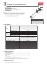
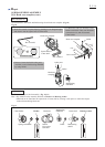
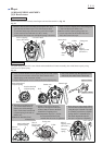
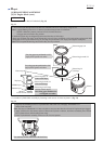
(1) Remove Plug cap from Spark plug and test the continuity
between Plug cap spring in Plug cap and Earth terminal of
Ignition coil.
It is in order when Tester shows 2.0kΩ±0.5kΩ.(Fig. 15)
(2) In case of no continuity or unstable continuity, check the
connection between Plug cap spring and Ignition coil as follows:
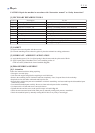
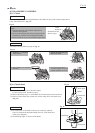
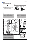
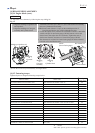
(A) Spray the lubricant in Plug cap, then pull out Plug cap spring
together with Ignition cable using Long-nose pliers. (Fig. 16)
(B) In case no connection or inconsistent connection,
check the condition of Plug cap and spring.
Reassemble them or replace them if they are disorder.
(C) Insert the end of Plug cap spring into Ignition cable, then return them
back to the inside of Plug cap carefully so as not to be disconnected.
(D) Check Plug cap and spring again according to the step of (1) to avoid
poor connection causing the poor sparks of Spark plug.
ASSEMBLING OF IGNITION COIL
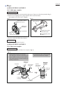
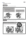
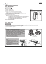
(1) Insert 0.3mm Feeler gauge of 1R366 in between the
magnet portion of Flywheel and Ignition coil. Tighten M4x20
Hex socket head bolts (2pcs) while keeping Ignition coil
attached to Flywheel through 0.3mm thickness gauge.
Note: Two M4x20 Hex socket head bolts (Fig. 19) are with
threadlocker. Therefore, when re-using them, apply
ThreeBond 1342 or Loctite 242 to the threads.
(2) After setting Ignition coil, remove the thickness gauge, then
turn Flywheel by hand to check if it turns smoothly
without being stuck.
Note: Be sure to insert Spacer on M4x20 Hex socket head bolt
when fastening Ignition coil to Engine. (Fig. 18)
(3) Assemble Cylinder cover to Engine.
Fig. 15
Fig. 16
Fig. 17
Fig. 18
Fig. 19
CHECKING PLUG CAP
(1) Remove Plug cap with Plug cap spring, then remove Spark plug with Box
driver 15-17 (standard equipment).
Note: If the electrodes are wet with Fuel, wipe it away with a cloth and
dry it by air blow.
(2) Clean carbon deposits on Electrodes on Insulator tip with a wire brush.
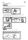
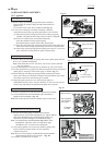
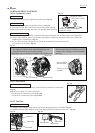
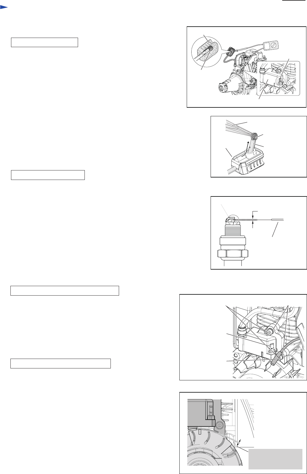
(3) Do fine adjustment of a gap between Side electrode and Center electrode of
Spark plug by inserting 0.7mm Feeler gauge of 1R366. (Fig. 17)
(4) Mount Plug cap with Plug cap spring on Plug terminal and connect
Screw part of Plug to a metal part of Engine, then pull Starter rope slowly.
The sparks can be seen when starter rope is pulled.
(5) When the sparks can not be seen, follow the procedure of
[CHECKING PLUG CAP] to test the continuity. If it has yet to be solved,
replace Plug and recheck the ignition through the above process.
CHECKING SPARK PLUG
(1) Remove Cylinder cover and cable from Ignition coil terminal.
(2) Loosen M4x20 Hex socket head bolts (2pcs) and remove
Ignition coil from Engine. (Fig. 18)
Note: Do not lose Spacers for heat insulation (2pcs) on the bolts.
DISASSEMBLING OF IGNITION COIL
0.6 up to 0.7mm
Plug cap spring
Plug cap
Ignition cable
Long-nose pliers
Clearance between
Flywheel and
Ignition coil: 0.3mm
Plug cap
Ignition coil
Earth terminal
M4x20 Hex socket
head bolt (2pcs.)
Spacer (2pcs.)
Tab of Ignition
coil to connect
with Cable
Connector
of Cable
Plug cap spring
Repair
P 7/ 14
0.7 mm Feeler
gauge of 1R366
Electrode