


[4] DISASSEMBLY/ASSEMBLY
[4]-14. Engine block (cont.)
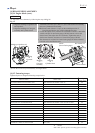
Fig. 33
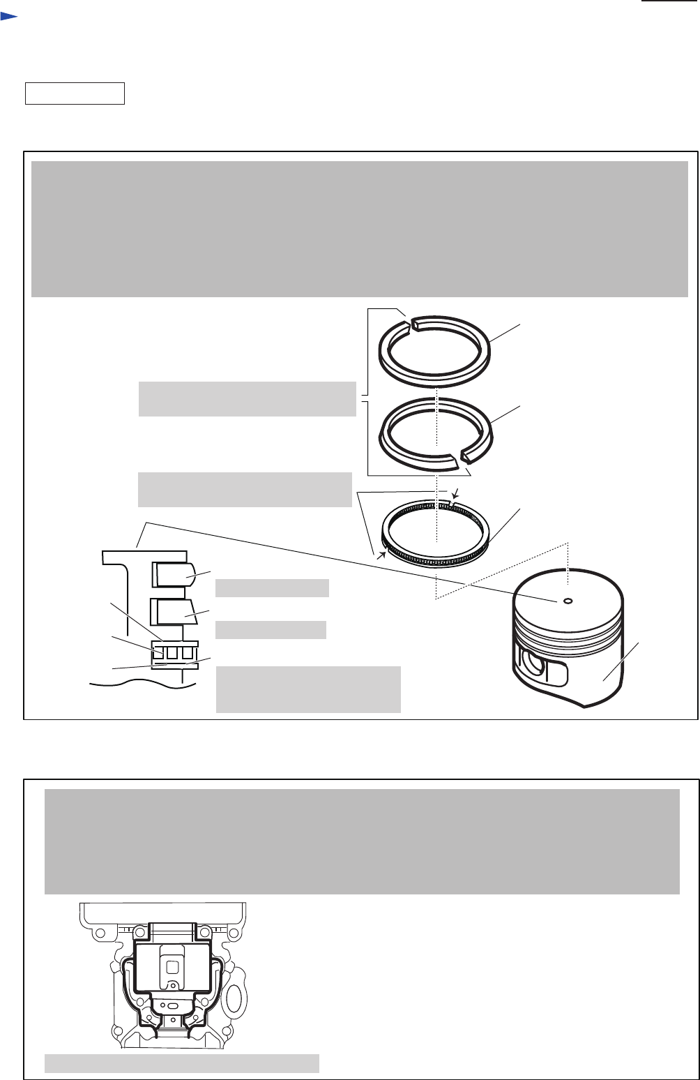
Fig. 34
ASSEMBLING
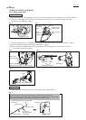
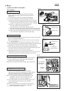
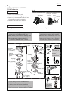
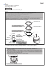
Piston ring (top) 34
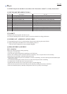
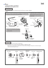
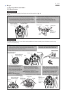
(1) Assemble Piston to Rod of Crankshaft. (Fig. 33)
(2) Assemble Cylinder block assembly by fastening it with screws in crisscross pattern. (Fig. 34)
Piston ring (top) 34
Center-rised shape
Piston top end
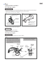
Bottom layer
Middle layer
Top layer
The matching surface; indicated with black lines
Piston ring (second) 34
Wide-based shape
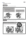
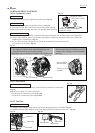
Two ring gaps are positioned at 180
°
angle points against each other.
Two ring gaps are positioned at 120
°
angle points against each other.
Cross section of Piston
Piston ring (second) 34
Piston ring 34
(Oil ring)
Piston ring 34 (Oil ring)
consists of three layers.
Note: Ring gaps should not be
overlapped each other.
Piston
Repair
P 13/ 14
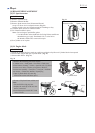
1. Insert Piston pin through Piston and Rod of Crankshaft, and fix it with Clip by using an awl.
Note: • Apply Makita grease N No.2 a little to Needle bearing in Rod of Crankshaft.
• Piston is bilateral symmetry and can be fixed in either direction.
• Clip gap can be located at any position.
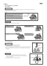
2. Install all piston rings at designated position and direction as followings:
• Ring gaps of Piston ring (top) 34 and Piston ring (second) 34 are positioned at 180º angle points against each other.
• Ring gaps of two layers of Piston ring 34 (Oil ring) are positioned at 120º angle points against each point.
Note: Do not expand Piston rings too much as they are easy to break.
1. Degrease the matching surface of Cylinder block and Crank case, and apply ThreeBond 1215
on the Crank case side.
Note: The layer of ThreeBond 1215 has to be thin so as not to enter into the oil route in Engine and get clogged.
2. Apply 4-stroke oil to the contact surface of Piston and Cylinder. And then, install the assembled part of Piston
into Cylinder block, while holding Piston rings.
3. Fasten Cylinder block assembly with screws in crisscross pattern.