


[4] DISASSEMBLY/ASSEMBLY
[4]-10. Carburetor
DISASSEMBLING
CLEANING / MAINTENANCE
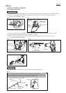
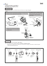
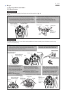
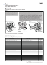
(1) Remove Air cleaner cover and
disassemble Air cleaner. (Fig. 24)
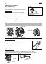
(2) Remove H.S. button head bolt M5x60 (2pcs)
completely, then disassemble Carburetor and
Cleaner plate assembly from Insulator.
(3) Disconnect two tubes from Carburetor.
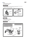
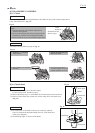
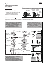
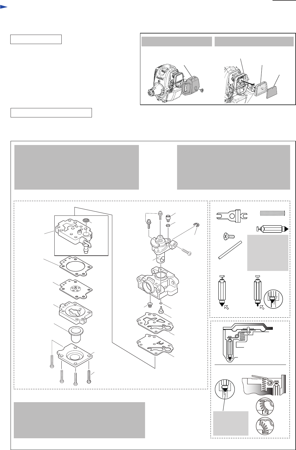
Fig. 25
Carburetor Controller set
3x24 Tapping
screw (4pcs.)
Primer pump
cover
Primer pump
Air purge body
Pump body
(M3x4 + screw
is included.)
Pump
diaphragm
Pump gasket
Jet
O ring 2
Conical
compression
spring 5-9
Inlet
screen
M3x8 Pan head screw
with washer
(2pcs)
Swivel
Stop ring
E-3
Washer
Metering
diaphragm
Metering
diaphragm
gasket
(Throttle valve
assembly)
Correct Wrong
Pin
Control lever
Spring
Inlet needle
Note:
These items can
not be supplied
separately.
Order Pump body
to replace them.
M3x4 screw
Correct
Wrong
Dust in Pump
body causes
the leakage of
pressure.
Idling screw
Repair
P 10/ 14
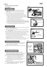
(1) Do regularly Carburetor cleaning and maintenance by following the procedure in Fig. 25.
1. Remove 3x24 Tapping screws (4pcs) and Primer
pump cover, then Diaphragm gasket set.
Note: Carefully remove Metering diaphragm when
the Gasket sticks to it as it’s fragile .
2. Replace Metering diaphragm when it is:
• slackened, • hardened, • worn, • debased.
5. Loosen Idling screw fully first, then remove
M3x8 P.H. screws (2pcs.).
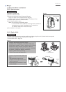
6. Check and clean Inlet screen before fitting.
7. Spray Carburetor cleaner each inlet openings and
leave it for a minutes, then wash them with gasoline.
3. Disassemble Controller set by removing
a M3x4 screw from Pump body assembly.
Note:Check the tip of Inlet needle if it is worn
or deformed before assembling.
4. Make sure if Spring is set on the projection
of Control lever when they are assembled.
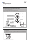
Fig. 24
Air cleaner
cover
Air cleaner
element
(sponge)
Air cleaner
element
(felt)
Cleaner plate
assembly
1. Remove Air cleaner cover. 2. Remove Air cleaner elements.