


37
Section 4: Options & Accessories
10/21/15
RC4015 and RCM4015 Series 2 S/N 944961+ Rotary Cutters 330-845M
Table of Contents
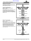
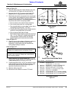
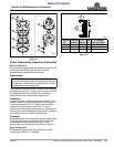
12. Red wires in connectors (#1A & #1B) are attached to
pin “D” shown in Detail B. Plug connectors (#1A &
#1B) together.
13. Yellow wires in connectors (#2A & #2B) are attached
to pin “B” Shown in Detail B. Plug connectors (#2A &
#2B) together.
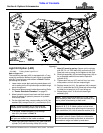
14. Route wire harnesses (#17 & #18) to enhance
module (#19). Plug connectors at the enhance
module to harness (#17 & #18) as follows:
a. Red wires in connectors (#1C & #1D) are
attached to pin “B” as shown in Detail B. Plug
connectors (#1C & #1D) together.
b. Yellow wires in connectors (#2C & #2D) are
attached to pin “C” shown in Detail B. Plug
connectors (#2C & #2D) together.
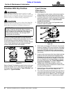
15. Attach connector (#3A) to connector (#3B) on lead
wire harness (#20).
16. Route lead wire harness through spring hose
loop and connect to the tractor’s 7-way round pin
receiver.
17. Start tractor and operate lights to verify hook-up is
operating properly:
a. Turn on head lights to verify red lights illuminate.
b. Operate turn signal to turn right. Amber light on
the right side should blink on and off.
c. Operate turn signal to turn left. Amber light on the
left should blink on and off.
18. If the lights did not operate properly, recheck hook-up
of wire harnesses (#17 & #18). Make necessary
changes to the harnesses and repeat step 17 above.
19. Recheck wire harness routing to make sure wires will
not be pinched as wing decks are folded and
unfolded and while raising and lowering cutter height.
20. Add cable ties (#5) to wire harnesses (#17, #18, &
#20) as needed to secure them in place.