


21
Section 1: Assembly & Set-up
10/21/15
RC4015 and RCM4015 Series 2 S/N 944961+ Rotary Cutters 330-845M
Table of Contents
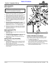
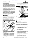
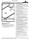
Driveline Clearance Check
Check driveline for adequate clearance under all ranges
of cutter height.
1. With driveline shaft attached to the tractor and all
stroke control spacers (#4 in Figure 1-22) removed
from hydraulic cylinder (#1), slowly raise and lower
cutter to its upper and lower limits while observing
clearances between hitch and driveline. Adjust
tractor drawbar height and/or length if driveline
interferes. See Figure 1-1 on page 11 for correct
drawbar dimensions.
2. It may be necessary to purge lift cylinder, wing
cylinder, and hydraulic hoses of trapped air if
operation is sluggish. Cycle cylinders back and forth
several times to purge air from them. For additional
details, see “Purge Hydraulic System” below.
Purge Hydraulic System
!
DANGER
Never remove or install a folding wing cylinder with cylinder
rod retracted and wing folded up. The wing is unstable without
its folding cylinder and can suddenly fall. Also, air trapped in
a new or repaired cylinder will drop the wing suddenly when
lowering the wing. Either situation can render the cutter
inoperable and cause serious bodily injury or death.
!
WARNING
Be sure center and wing decks are lowered to the ground and
all hydraulic pressure is relieved before disconnecting any
hydraulic lines or fittings between the Rotary Cutter and
tractor hydraulic system.
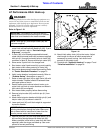
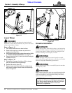
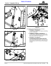
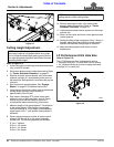
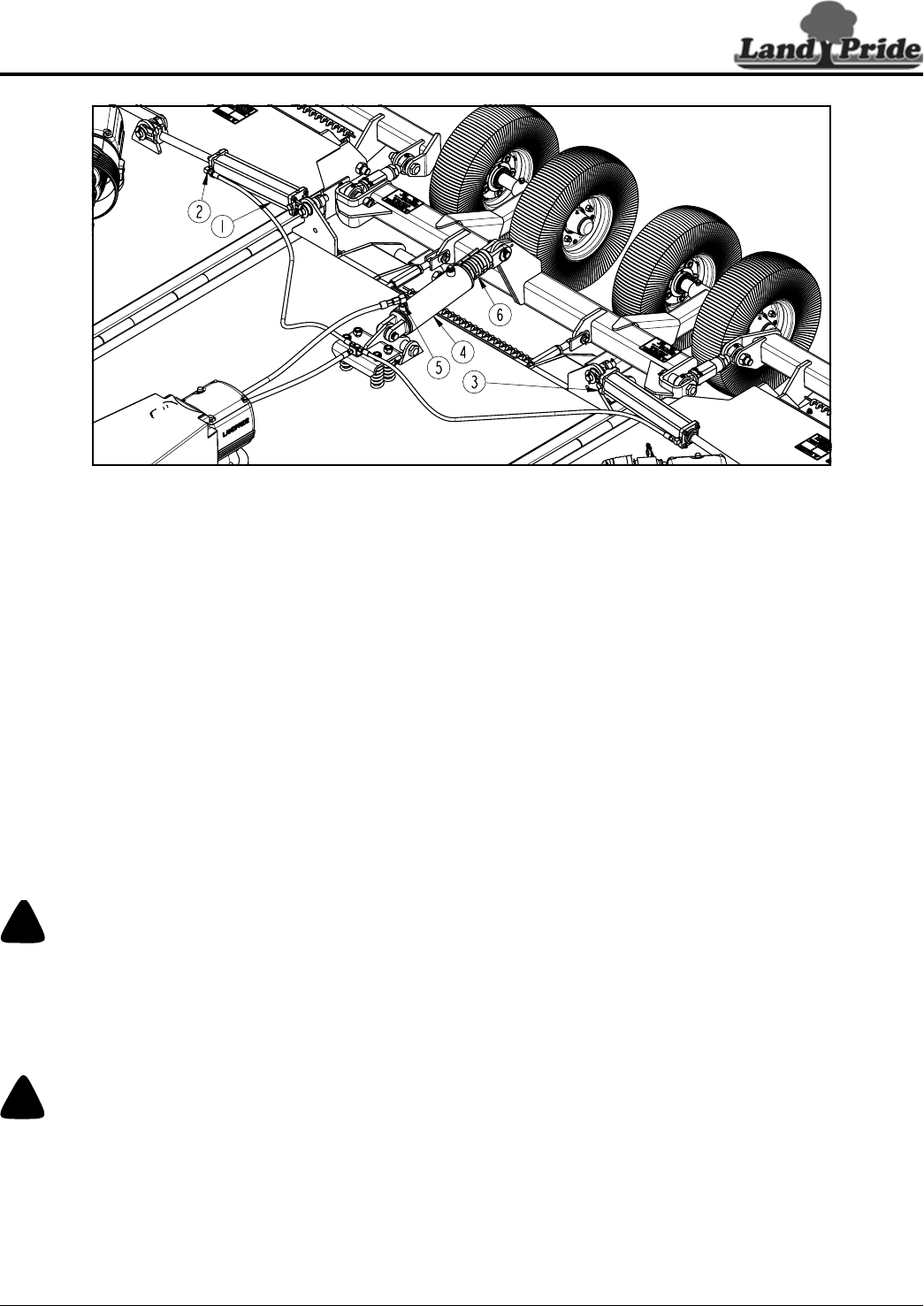
Refer to Figure 1-23:
Wing Fold Cylinder
1. Lower center deck until it is supported by stroke
control spacers (#6) on hydraulic cylinder (#4).
2. Lower wing decks until they are resting on the
ground.
3. See “Tractor Shutdown Procedure” on page 13.
Shut tractor down properly and move wing control
levers back and forth to relieve all hydraulic pressure.
4. Slightly loosen hydraulic hose fitting (#2) at right-
hand wing cylinder (#1) to allow air to escape.
5. Restart tractor and slowly activate tractor control
lever to retract wing cylinder (#1), and to purge
trapped air from the hydraulic system.
6. Repeat steps 1 thru 3 above once air is purged from
the right-hand wing cylinder.
7. Tighten hose fitting at the right-hand wing cylinder.
8. Repeat steps 4 thru 7 above to purge the left-hand
wing cylinder (#3).
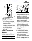
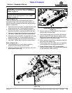
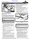
Deck Lift Cylinder
Refer to Figure 1-23:
1. Lower center deck until it is supported by stroke
control spacers (#6) on hydraulic cylinder (#5).
2. See “Tractor Shutdown Procedure” on page 13.
Shut tractor down properly and move deck lift control
lever back and forth to relieve all hydraulic pressure.
3. Slightly loosen hydraulic hose fitting (#5) at deck lift
cylinder (#4) to allow air to escape.
4. Restart tractor and slowly activate tractor control lift
lever to extend lift cylinder (#4) and to purge trapped
air from the hydraulic system.
5. Repeat steps 1 & 2 above once air is purged from the
deck lift hydraulic system.
6. Tighten hose fitting (#5) at lift cylinder (#4).
Purge Wing cylinders & Deck Lift Cylinder
Figure 1-23