


24
Section 2: Adjustments
RC4015 and RCM4015 Series 2 S/N 944961+ Rotary Cutters 330-845M
10/21/15
Table of Contents
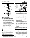
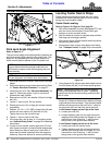
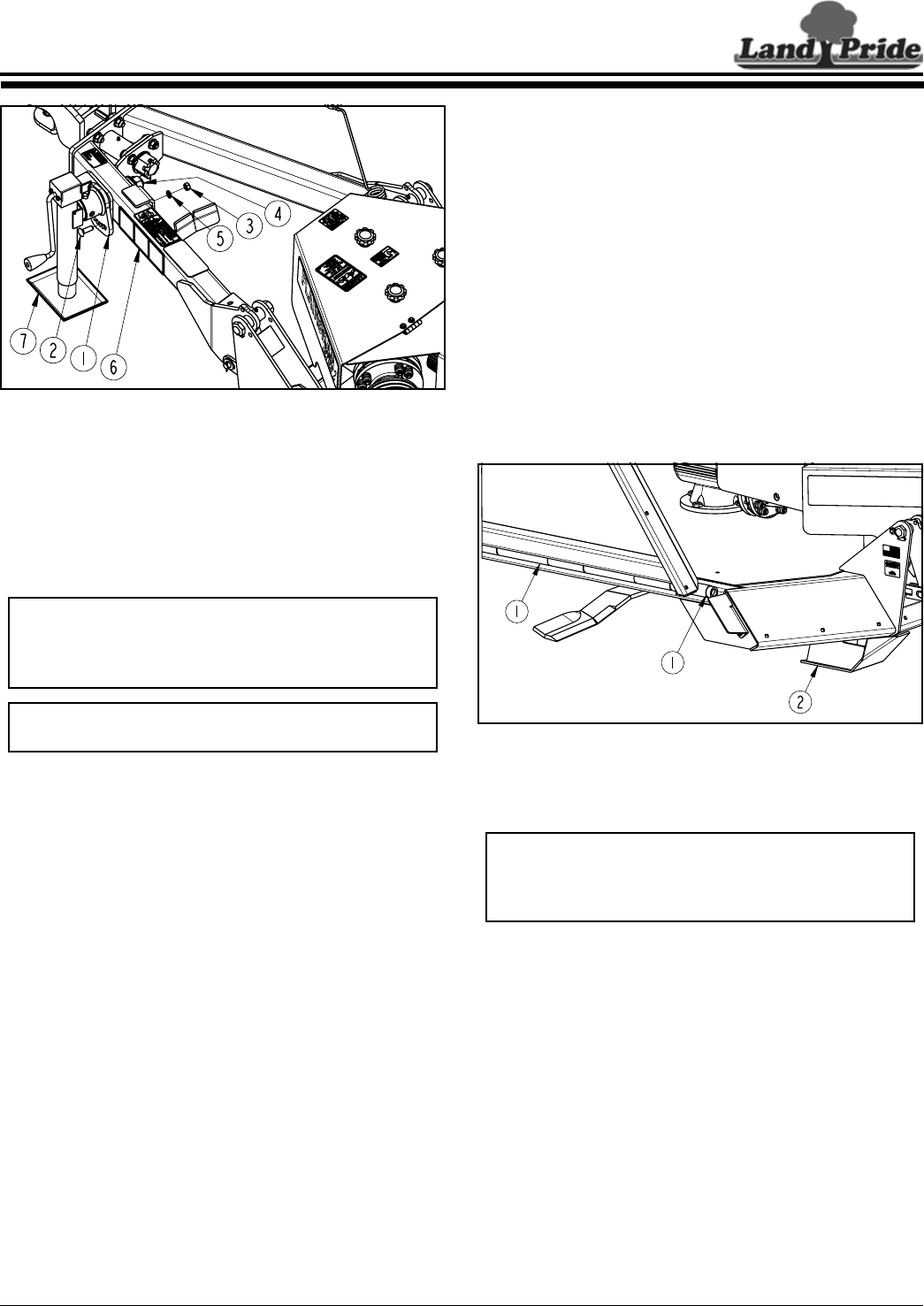
Park Jack Angle Alignment
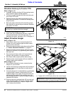
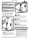
Figure 2-1
Park Jack Angle Alignment
Refer to Figure 2-1:
The jack mount angle should be adjusted to position the
park jack vertical while supporting the cutter hitch. This
angle will vary depending on the number and size of
stroke control spacers placed on the lift cylinder rod.
1. With cutter hitched to a tractor, lower cutter to storage
height.
2. Shut tractor down properly before dismounting. Refer
to “Tractor Shutdown Procedure” on page 13.
3. Install park jack (#7). See “Park Jack Assembly” on
page 13. Check jack angle. If jack is not vertical,
proceed with step 3 below.
4. Remove hex nut (#3), lock washer (#5) and carriage
bolt (#2).
5. Loosen 1" hex nut (#4). Do not remove.
6. Rotate jack mount (#1) to align jack as near vertical
as possible.
7. Replace 1/2"-13 x 1 1/2" GR5 carriage bolt (#2) and
secure with lock washer (#5) and hex nut (#3).
Tighten hex nut to the correct torque.
8. Tighten 1" hex nut (#4) to 645 ft-lbs.
9. If moving cutter, skip to step 10. If unhooking cutter,
see “Unhook Rotary Cutter” on page 22 for detailed
instructions.
10. If cutter is to be moved, remove park jack (#7) from
hitch frame and attach it to the left-hand wing storage
base. Make sure base of park jack is level with or
lower than the head, especially after the wings are
folded up. See cover picture for correct positioning.
37576
NOTE: If cutter is not hitched securely to a tractor,
support blocks should be placed under the front
skid shoes to support cutter while aligning the park
jack vertically.
NOTE: Refer to decal (#6) and instructions below
for jack alignment and torque value instructions.
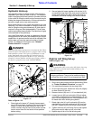
Leveling Center Deck & Wings
These adjustments should be made with your cutter
hooked to the tractor operating the unit or to a tractor
having the same drawbar height.
Center Deck Leveling
Refer to Figure 2-2 & Figure 2-3 on page 25:
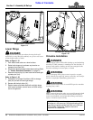
1. With cutter attached to a tractor, disengage PTO, and
park on a level, hard surface. Place tractor gear
selector in park or set park brake.
2. Wait for blades to come to a complete stop and then
fold wings up to transport position.
3. Shut tractor engine off and remove switch key before
dismounting from tractor.
4. Set transport locks to keep wing decks from falling.
See “Transport Locks” on page 30 for instructions.
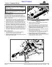
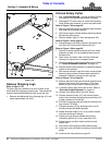
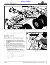
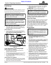
Front Skid Position (Chain Guards Removed for Clarity)
Figure 2-2
5. Using hydraulic lift, adjust center deck height so that
the front skids (#2) are 2 to 3 inches above ground.
6. On both sides of the center deck are continuous
hinges (#1). Measure distance from bottom of hinges
to ground at the front and back. They should be equal
distance off the ground at the back and 1" closer to
the ground at the front than they are at the back.
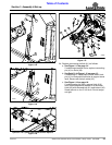
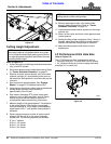
If continuous hinges are too high at the front:
a. Loosen jam nuts (#3).
b. Loosen adjusting nuts (#4) an equal amount to
lengthen both leveling rods until hinges (#1) are
inclined from front to back by 1" with the front
being closer to the ground than the back.
If continuous hinges are too low at the front:
a. Loosen jam nuts (#3) several turns.
b. Tighten adjusting nuts (#4) an equal amount to
shorten both leveling rods until hinges (#1) are
inclined from front to back by 1" with the front
being closer to the ground than the back.
27858
NOTE: Loosening coupler nuts (#4) will lengthen
leveling rods and lower front of cutter. Tightening
coupler nuts (#4) will shorten leveling rods and raise
front of cutter.
Section 2: Adjustments