


17
Section 1: Assembly & Set-up
10/21/15
RC4015 and RCM4015 Series 2 S/N 944961+ Rotary Cutters 330-845M
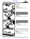
Table of Contents
Hydraulic Hook-up
The required number of duplex outlets at the tractor is
dependent upon how the cutter is set-up. The standard
cutter is equipped with three hydraulic cylinders with one
in the center for lifting the cutter and one on each wing for
folding the wings simultaneously. All three cylinders are
set-up for single action (one-way) operation.
Each duplex outlet on your tractor can perform only one
operation. One outlet is needed for lifting the cutter and
one for lifting the wings simultaneously. A third outlet is
required if wings are lifted independently. This will also
require replumbing wing cylinders. Float position is highly
recommended for wing outlet(s).
Your Land Pride dealer can help you determine the best
configuration that will match your needs and your tractor
capabilities. An optional control valve kit is available if the
tractor does not have the required number of duplex
outlets. For additional information, see “Selector
Control Valve Kit” on page 35.
!
DANGER
Hydraulic fluid under high pressure can penetrate skin. Wear
protective gloves and safety glasses or goggles when working
with hydraulic systems. Use a piece of cardboard or wood
rather than hands when searching for hydraulic leaks. If
hydraulic fluid is injected into the skin or eyes, it must be
treated by a doctor familiar with this type of injury within a
few hours or gangrene may result. DO NOT DELAY.
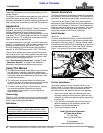
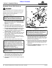
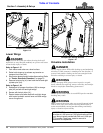
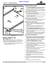
Hydraulic Hook-up (LP Performance Hitch Shown)
Figure 1-15
Refer to Figure 1-15:
1. Route hydraulic hoses (#7) through hose support
loop (#10) and attach couplers to the tractor remote
outlets. If tractor has a float option on one of the
outlets, connect wing lift hose to that outlet and set
tractor control lever for that outlet in float position
before cutting.
37631
2. Secure hydraulic hoses together with zip ties (#12)
as needed to keep them from pinch areas caused by
raising and lowering the deck, folding the wing up
and down, and while making turns with the tractor.
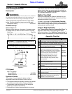
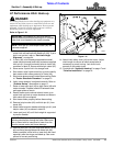
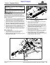
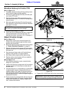
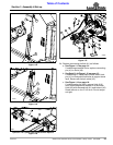
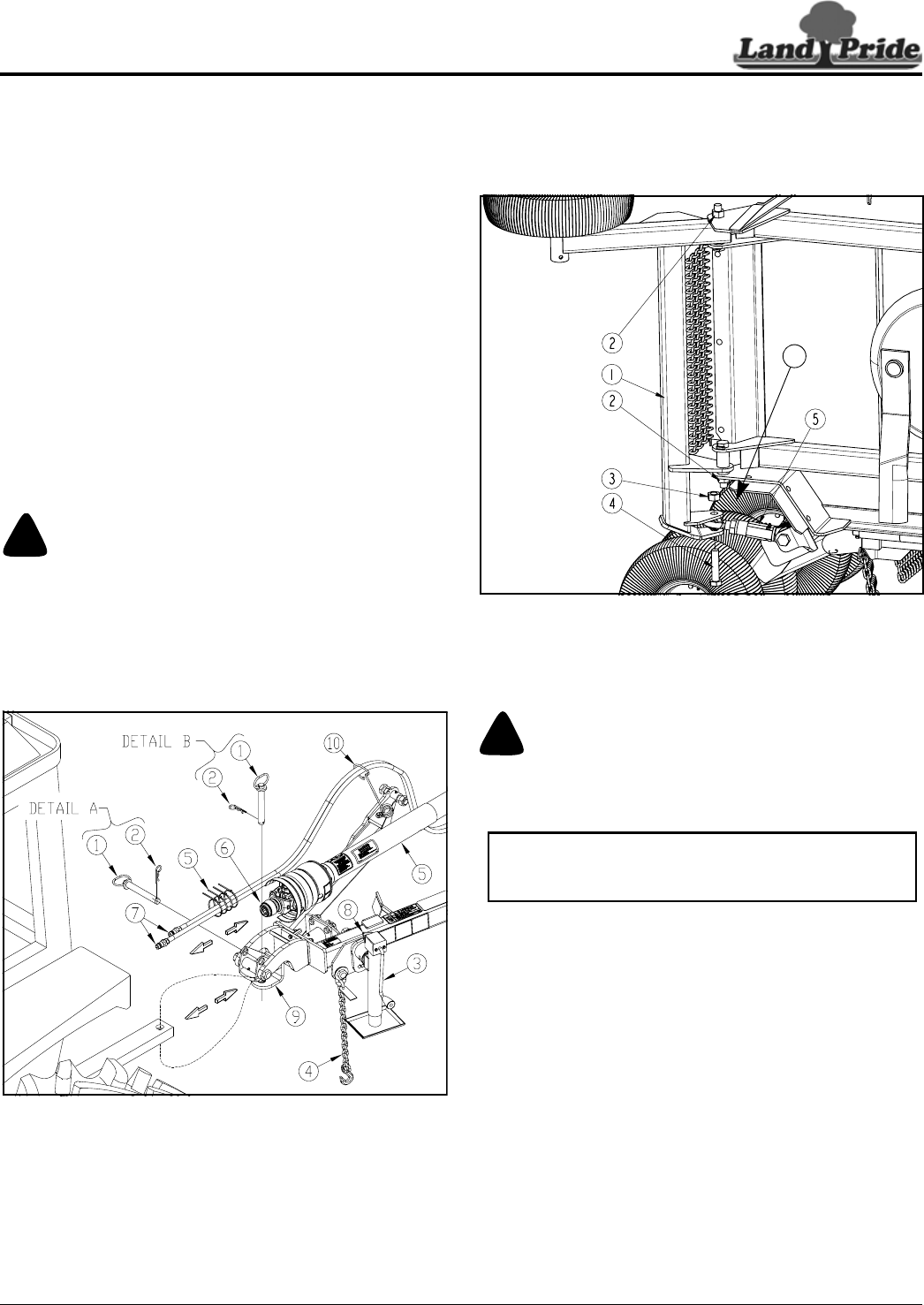
Wing Axle - Turnbuckle Assembly
Figure 1-16
Right & Left Wing Set-up
Refer to Figure 1-16:
!
WARNING
Connect turnbuckles (#5) to wing axles (#1) before lowering
wings. Otherwise, personal injury and/or damage to the
turnbuckle can occur.
1. Park tractor and cutter on a level surface.
2. Shut tractor down properly before dismounting. Refer
to “Tractor Shutdown Procedure” on page 13.
3. Cut metal band between the two wing axles.
4. On the right wing axle, loosen lock nuts (#2) slightly
to allow rotation of the axle.
5. Remove locknut (#3) and 1 1/4" hex head bolt (#4).
6. Loosen jam nut (#6) on turnbuckle (#5) and adjust
until center of ball swivels are approximately 10 1/2"
apart. Do not retighten jam nut. Final adjustment will
be made later when leveling wing decks.
7. Rotate right axle (#1) until turnbuckle (#5) can be
attached to the axle with existing bolt (#4) and lock
nut (#3). Tighten locknut (#3) to the correct torque.
8. Tighten locknuts (#2) until snug. Do not over tighten.
Wing axle must be able to pivot in the field.
9. Repeat steps 4 thru 6 for the left wing axle.
27929
6
NOTE: Wing axle locknuts (#2) are tightened for
shipping purposes. They must be loosened slightly
to allow the axle to pivot. Do not torque them tight.