


26
Section 5: Maintenance & Lubrication
RCD1884 Rotary Cutters 326-355M
12/15/15
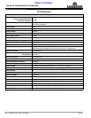
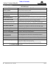
Table of Contents
Driveline Protection
The drive-train is protected from shock loads with a four
plate slip-clutch. The slip-clutch must be capable of
slippage during operation. Always do a “clutch run-in”
operation at the beginning of each season and after long
periods of inactivity to remove any oxidation that may
have accumulated on the friction surfaces. Repeat
“clutch run-in” instructions when moisture and/or
condensation seizes the inner friction plates.
!
WARNING
Always disengage PTO, engage parking brake, shut off
tractor, remove ignition key, and wait for all moving parts to
come to a complete stop before dismounting tractor to make
adjustments.
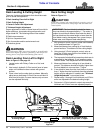
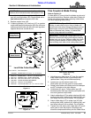
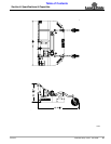
Clutch Run-In
Refer to Refer to Figure 5-4:
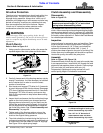
1. Using a pencil or other marker, scribe a line across the
exposed edges of the clutch plates and friction discs.
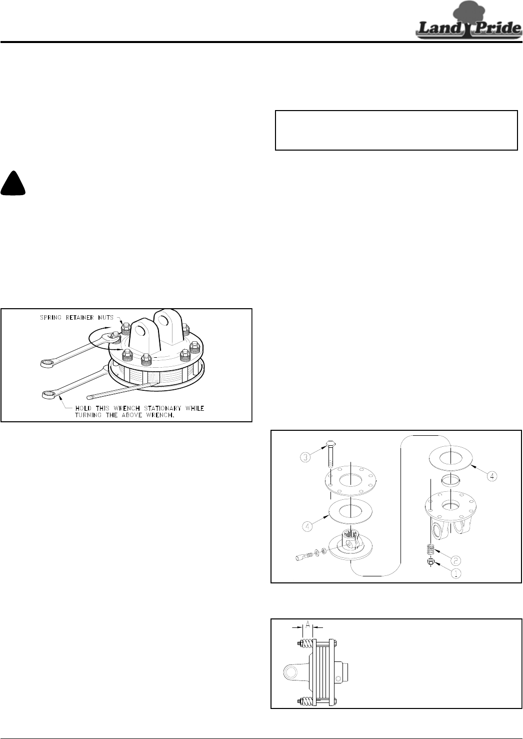
Clutch
Figure 5-4
2. Carefully loosen each of the 8 spring retainer nuts by
exactly 2 revolutions. It will be necessary to hold hex
end of retainer bolt in order to count the exact
number of revolutions.
3. Start tractor and engage PTO drive for 2-3 seconds
to permit slippage of the clutch surfaces. Disengage
PTO, then re-engage a second time for 2-3 seconds.
Disengage PTO, shut off tractor, and remove key.
Wait for all components to stop before dismounting
from tractor.
4. Inspect clutch and ensure that the scribed markings
made on the clutch plates have changed position.
Slippage has not occurred if any two marks on the
friction disc and plate are still aligned. A clutch that
has not slipped must be disassembled to separate
the friction disc plates. See “Clutch Assembly and
Disassembly” on page 26.
5. Tighten each of the 8 spring retainer nuts on the
clutch housing exactly 2 revolutions to restore the
clutch to the original setting pressure.
6. The clutch should be checked during the first hour of
cutting and periodically each week. An additional set
of scribe marks can be added to check for slippage.
See Figure 5-6 to adjust spring length.
13693
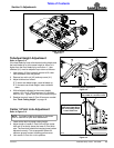
Clutch Assembly and Disassembly
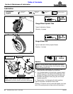
Disassembly
Refer to Figure 5-5:
See IMPORTANT NOTE above before disassembling
clutch. After measuring and recording each spring length,
remove spring retainer nuts (#1), springs (#2), and bolts
(#3). Each friction disc (#4) must then be separated from
the metal surface adjacent to it. Refer to the Parts Manual
for a detailed parts breakdown.
Inspection
Inspect all parts for excessive wear and condition. Clean
all parts that do not require replacement.The original
friction disc thickness is 1/8" (3.2mm) and should be
replaced if thickness falls below 3/64" (1.1mm). If
clutches have been slipped to the point of “smoking”, the
friction discs may be damaged and should be replaced.
Heat build-up may also affect the yoke joints.
Assembly
Refer to Figure 5-5 & Figure 5-6:
Reassemble each friction disc (#4) next to the metal plate
it was separated from. Install bolts (#3) through the end
plates and intermediate plates as shown. Place springs
(#2) over bolts (#3) and secure with nuts (#1).
Progressively tighten each spring retainer bolt until
correct spring height “A” dimension is obtained.
Clutch Disassembly
Figure 5-5
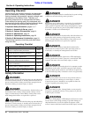
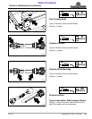
Clutch Adjustment
Figure 5-6
IMPORTANT: Refer to Figure 5-6. Be Sure to
measure and record length (“A”) of each clutch
spring before disassembling clutch.
33024
24600
A = Measured length of each spring
before disassembling slip clutch.
Use 1.27" for “A” dimension if
measurements were not taken
before disassembling slip clutch.