


10
Section 1: Assembly & Set-up
RCD1884 Rotary Cutters 326-355M
12/15/15
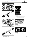
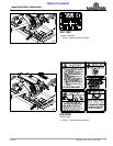
Table of Contents
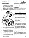
8. Rotate outer coupler shield closed and replace
existing hand knobs (#14). Hand tighten hand knobs.
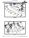
Tractor Hook-Up
Refer to Figure 1-3 on page 11:
!
DANGER
A Crushing Hazard exists when hooking-up equipment to a
tractor. Do not allow anyone to stand between tractor and
implement while backing-up to implement. Do not operate
hydraulic 3-point lift controls while someone is directly
behind tractor or near implement.
A 3-Point Category I or II hitch is required. The lower
3-Point arms of the 3-Point hitch must be stabilized to
prevent side-to-side movement. Most tractors have sway
blocks or adjustable chains for this purpose.
1. Locate cutter on a flat level surface.
2. Slowly back tractor up to Rotary Cutter while using
tractor’s 3-Point hydraulic control to align lower
3-Point arm holes with clevis lug holes on the cutter.
3. Engage tractor park brake, shut tractor engine off,
and remove key before dismounting from tractor.
4. Attach lower arms to clevis plates with hitch pins and
secure with linch pins.
5. Connect top center 3-Point link to upper pivot hitch
with clevis pin and hairpin cotter supplied by the
customer.
6. Return to the tractor. Slowly raise and lower
implement carefully to ensure that the drawbar, tires,
and other equipment on the tractor do not contact
cutter frame. Move or remove drawbar if it interferes
with the cutter.
7. Manually adjust one of the two lower lift arms up or
down to level the Rotary Cutter from left to right.
8. Manually adjust the length of the top-link to level the
Rotary Cutter from front to rear. Final deck leveling
adjustments will be made later.
9. The 3-Point lift cylinders on your tractor should be
adjusted to allow for lateral float. Please consult you
tractor’s manual for adjusting instructions.
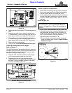
Quick Hitch Hook-up
Refer to Figure 1-4 on page 11:
If 3-Point hitch plates won’t stay upright for Quick Hitch
attachment, a hitch pin or bolt (#1) may be inserted into
hole “A” to stabilize hitch plates. Be sure to remove hitch
pin before connecting driveline to the tractor. Hitch pin or
bolt is supplied by customer.
NOTE: Land Pride’s Quick Hitch can be attached to
the tractor to provide quick and easy 3-point hook-
up and detachment. See your nearest Land Pride
dealer to purchase a Quick-Hitch.
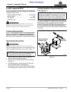
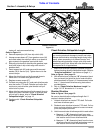
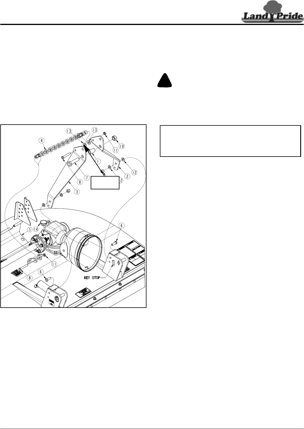
3-Point Hitch Assembly
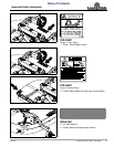
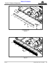
Refer to Figure 1-2:
1. Attach left-hand hitch plate (#2) to upper mounting
hole in clevis plate with 5/8"-11 x 1 3/4" GR5 cap
screw (#6), two flat washers (#12), and hex nylock
nut (#9). Draw nylock nut up snug, do not tighten.
2. Attach right-hand hitch plate (#3) to upper mounting
hole in clevis plate with 5/8"-11 x 1 3/4" GR5 cap
screw (#6), two flat washers (#12), and hex nylock
nut (#9). Draw nylock nut up snug, do not tighten.
3. Rotate top of hitch plates (#2 & #3) back until bottom
of hitch plates rest against the key stops.
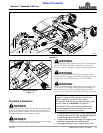
Hitch Assembly
Figure 1-2
4. Attach 2 1/16" long bushing (#1) to left and right-hand
hitch plates (#2 & #3) with 1"-8 x 4" GR5 hex head
cap screw (#7) and hex top locknut (#10).
Tighten top locknut (#10) to torque value listed under
“Additional Torque Values” on page 34.
5. Attach one end of float chain (#4) between hitch
plates (#2 & #3) with 9/16"-12 x 3 1/2" GR5 cap screw
(#8), two flat washers (#13), and hex top locknut
(#11). Draw locknut (#11) up snug, do not tighten.
6. Remove hand knobs (#14) and rotate flex coupler
shield open.
7. Attach opposite end of float chain (#4) to deck lugs
with 9/16"-12 x 3 1/2" GR5 cap screw (#8) and top
locknut (#11). Draw locknut up snug, do not tighten.
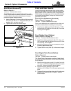
30998
Large Hole
to the Front