


25
Section 5: Maintenance & Lubrication
12/15/15
RCD1884 Rotary Cutters 326-355M
Table of Contents
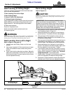
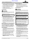
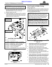
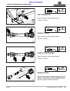
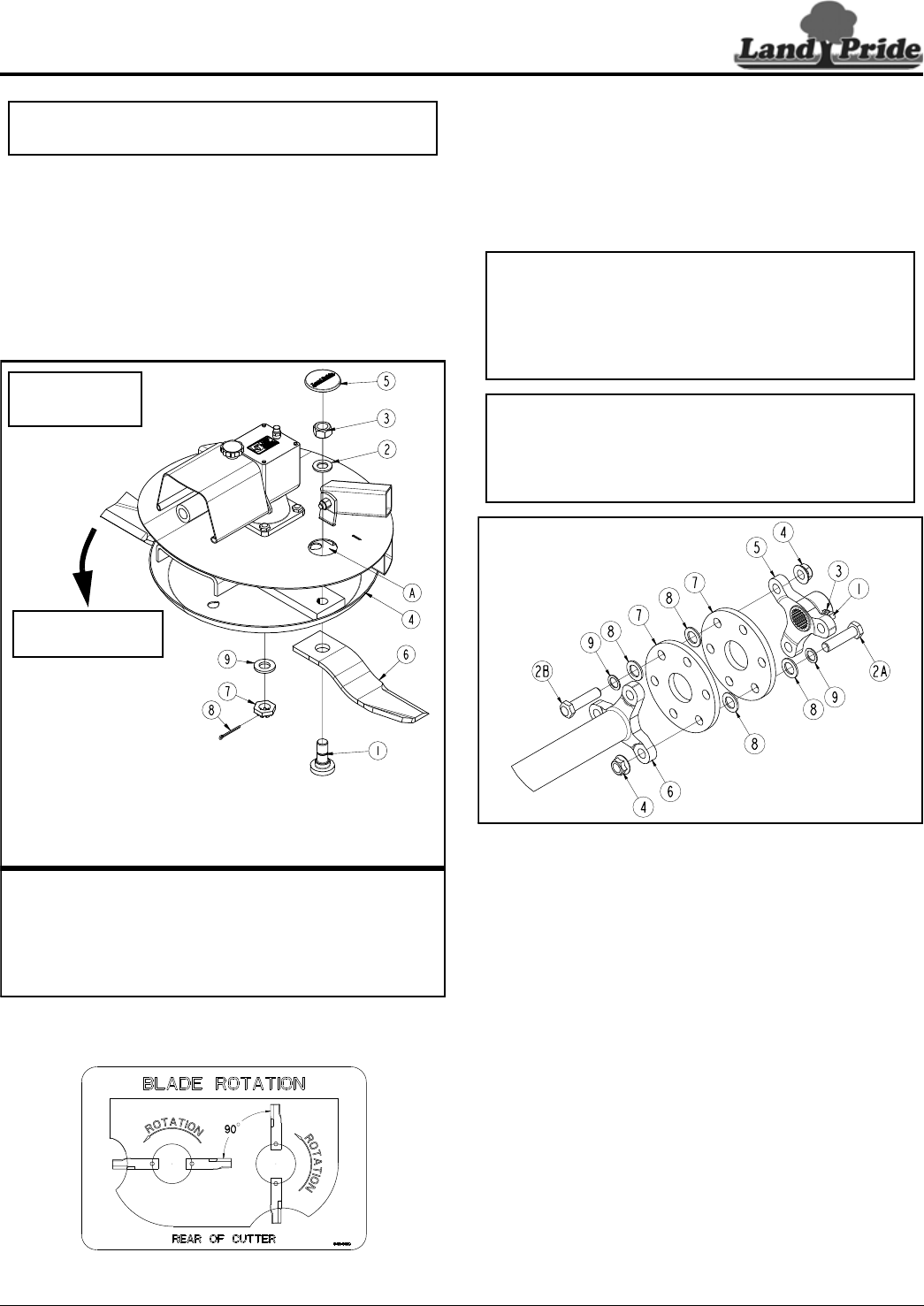
8. Insert blade bolt (#1) through blade (#6), dish
pan (#4), and flat washer (#2). Secure blade with a
new locknut (#3) and torque to 450 ft-lbs.
9. Replace access cover (#5).
10. If replacing dishpan (#4), castle nut (#7) on gearbox
output shaft should be torqued to 450 ft-lbs. minimum
and secured with cotter pin (#8) with both legs bent
opposite directions around the nut.
Cutter Blade Assembly
Figure 5-1
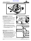
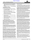
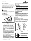
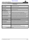
Blade Rotation & Timing
Figure 5-2
IMPORTANT: Examine blade bolts (#1) and flat
washers (#2) for excessive wear and replace if worn.
33002
Counterclockwise
Blade Rotation
Use 1-11/16"
Socket Wrench
On Blade Nut (#3)
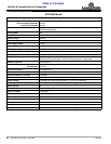
Land Pride Cutter Blade Parts
Item Part No. Part Description
318-586A BLADE BOLT KIT (items 1, 2, & 3 below)
1 802-277C BLADE BOLT 1 1/8-12 x 3 7/16 WITH KEY
2 804-147C WASHER FLAT 1 HARD ASTMF436
3 803-170C NUT HEX TOP LOCK 1 1/8-12 PLATE
4 326-234H ROUND DISHPAN WELDMENT
5 840-273C PLUG LP 3" ID RUBBER
6 820-443C CUTTER BLADES 1/2" x 4" x 16" LG. CCW
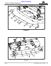
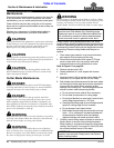
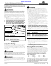
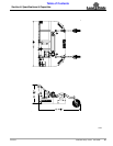
Flex Coupler & Blade Timing
Refer to Figure 5-3:
If rubber discs (#7) are wrinkled, the blades may be out of
time and hit each other. Replace rubber disc if blades hit.
Follow instructions below when replacing rubber discs
and when adjusting blade timing.
Flex Coupler Assembly
Figure 5-3
1. Unbolt/remove rubber discs (#7) from flex coupler.
Keep rubber discs that are in good shape and
replace them if they are wrinkled excessively.
2. Loosen jam nut (#3) and set screw (#1).
Slide spider (#5) off main gear box output shaft.
3. Rotate cutter blades until blades on the left dishpan
are 90
o
to blades on the right dishpan.
4. Hold blades 90
o
apart. Center spider lugs (#5)
between spider tube lugs (#6) and push spider (#5)
onto main gearbox output shaft.
5. Attach rubber discs (#7) to spider tube lugs (#6) with
existing bolts (#2A), washers (#9), bushing (#8), and
hex flange locknuts (#4) as shown. Do not tighten.
6. Attach rubber discs (#7) to spider lugs (#5) with
existing bolts (#2B), washers (#9), bushing (#8), and
hex flange locknuts (#4) as shown. Do not tighten.
7. Tighten nuts (#4) evenly until rubber disc (#7) touch
each other at each bolt location. Bushings (#8)
should be compressed halfway into the rubber discs.
IMPORTANT: See Figure 5-2. Cutter blades must be
90 deg. to each other to be in time or blades will
contact each other when hitting solid objects such as
tree stumps, rocks and earth. Blades hitting each
other will become bent, broken, or twisted and
require being replaced immediately.
IMPORTANT: Through use, rubber discs (#7) will
become wrinkled from hitting solid objects causing
blades to be out of time. Replace rubber disc when
wrinkling causes blades to make a ticking sound
from touching each other while cutting heavy brush.
33025