


9
Section 1: Assembly & Set-up
12/15/15
RCD1884 Rotary Cutters 326-355M
Table of Contents
Section 1: Assembly & Set-up
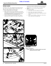
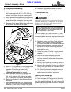
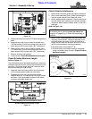
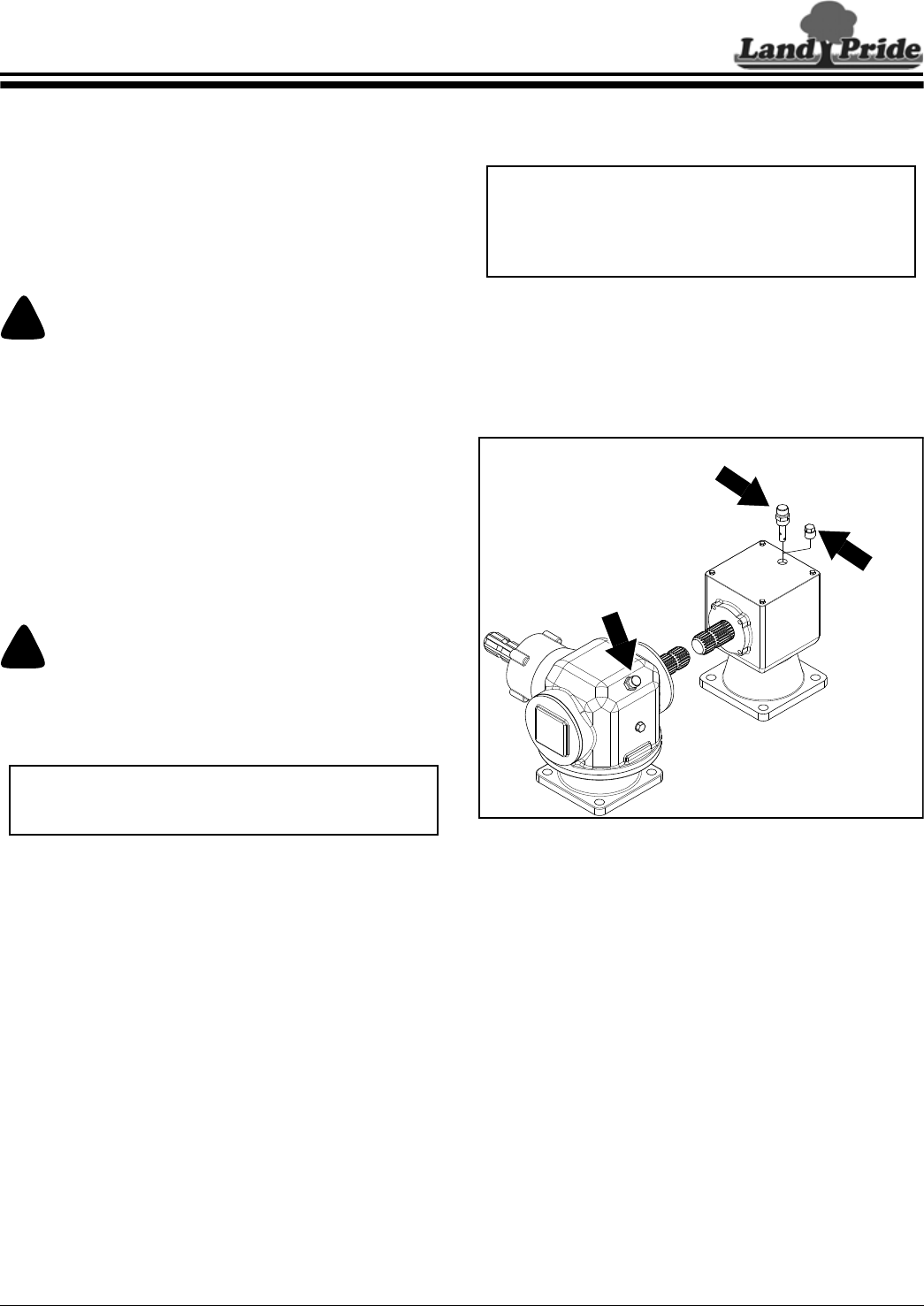
Vented Breather Plug Installation
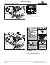
Refer to Figure 1-1:
The right angle gearbox is shipped with vented breather
plug factory installed. The other gearbox is shipped with
vented breather plug packaged with the Operator’s
Manual in the manual tube. Remove temporary solid plug
from top of gearbox and replace with vented breather
plug. See your nearest Land Pride dealer if breather plug
is missing.
Vented Breather Plug Installation
Figure 1-1
IMPORTANT: Rotary Cutters are shipped with a
solid plug in the gearbox to prevent loss of oil during
shipping and handling. The solid plug on top of the
gearbox must be replaced with a vented dipstick. Do
not operate cutter without vented dipstick installed.
33060
Remove
Solid Plug
Install Breather Plug During Assembly & Set-up
Factory Installed
Breather Plug
Tractor Requirements
Tractor horsepower and hitch category should be within
the range noted below. Tractors outside the horsepower
range must not be used.
Tractor Horsepower Rating. . . . . . . . . . . . 35 to 60 HP
Hitch Category . . . . . . . . . . . . . . . . . . . . . . . . . Cat I
PTO Speed . . . . . . . . . . . . . . . . . . . . . . . . .540 RPM
PTO Shaft Type . . . . . . . . . . . . . . . . . .1 3/8"-6 Spline
!
WARNING
Ballast weights may need to be added to your tractor to
maintain steering control. Refer to your tractor operator’s
manual to determine proper ballast requirements.
Torque Requirements
Refer to “Torque Values Chart for Common Bolt Sizes”
on page 34 to determine correct torque values when
tightening hardware. See “Additional Torque Values” at
bottom of chart for exceptions to common torque values.
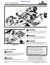
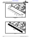
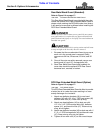
Uncrating Instructions
!
WARNING
Always secure cutter with an overhead crane, fork lift, or
other suitable lifting device before removing hardware bags,
shipping components, bands, lag screws, and hitch pins. The
cutter can suddenly fall causing serious injury or death.
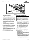
1. Secure cutter with a hoist or other lifting device
before removing shipping hardware.
2. Remove lag screws securing front face of cutter to
the crate.
3. Using lifting device, remove tension on hitch pins
securing clevis plates to shipping crate.
4. Remove hitch pins from clevis plates and lift cutter
from shipping crate. Gently lower unit onto the floor.
IMPORTANT: Do not attach hoist to gauge wheel
forks or gauge wheel arms near the spindles. The
arms and/or forks can bend when lifting cutter.