


33
Section 4: Maintenance & Lubrication
2-16/09
OS1548 and OS1572 Overseeder (S/N 166724+) 308-303M
Land Pride
Table of Contents
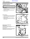
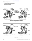
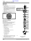
16. Apply a coat of grease to the seal and press bearing
housing assembly onto the rotor shaft, taking care
not to damage the seal. Reinstall snap ring.
17. Install rotor to the Overseeder by reversing steps 2
through 4.
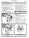
Rear Roller Maintenance
Refer to Figure 4-7:
Rear roller wheels (#14) should rotate freely over wheel
mounting tube (#15) and have a small amount of lateral
movement between the two end plates (#12). This loose
fit allows for the rollers to turn independently from each
other which keeps debri from locking them up and allows
the seeder to turn corners without pushing dirt in front of
the rollers.
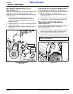
Rear Roller Inspection
Inspect roller wheels daily to make sure they are turning
and not pushing dirt. Your should be able to hold one
roller still while rotating the roller next to it with your hand.
If this cannot be done, then the rollers should be cleaned
of debri that has impacted between them.
Over time, the roller wheels will wear against each other
and become loose moving back and forth laterally on the
mounting tube. Spacers, 1/4" in width, should be added
on the left end to take up excessive slack and to extend
the life of the roller wheels and mounting tube. Also, the
roller wheels should be inspected for breakage. Broken
rollers should be replaced as soon as possible.
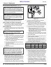
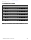
Inspect roller wheels for wear by sliding all rear roller
wheels (#14) and end spacers (#13) to the right and then
measure the gap on the left end. If gap between last end
spacer (#13) and end cap (#12) is 3/8" or greater, then an
additional 1/4" spacer or spacers should be added to the
mounting tube. Never add too many spacers. Too many
spacers will force the roller wheels tight against one
another and won’t allow them to turn independently.
Rear Roller Disassembly
Disassemble rear roller mounting tube from Overseeder
as follows:
1. Lower Overseeder and rear roller to ground, shut
tractor off, set park brakes and remove switch key.
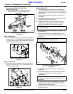
2. Disconnect packer chain (#6) or turnbuckle (#7) from
the left hand rear roller arm (#16).
3. Remove 3/8" bolts (#4) and scraper bar (#5) from left
and right rear roller arms (#16).
4. Remove 3/16" cotter pin (#8) and clevis pin (#9).
Lower front of left rear roller arm (#16) to the ground.
5. Loosen set screw in eccentric locking collar of
bearing (#10) and then rotate eccentric locking collar
counterclockwise. This should free the shaft from the
bearing.
NOTE: During disassembly, set aside all loose
components and hardware in an orderly fashion and
in a safe location for relocating and reassembling.
6. Remove rear roller arm (#16) with attached
bearing (#10) from rear roller mounting tube (#15).
7. Remove flat washer (#11) and end cap (#12).
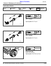
Rear Roller Assembly
1. Replace roller wheels (#14) and/or add 1/4" spacer
rings (#13) as needed on the left side of the seeder:
Roller Wheels
a. Remove roller wheels (#14) from mounting
tube (#15) until you reach the broken roller.
b. Replace broken roller with new roller and reinstall
removed roller wheels.
Spacer Rings
a. Add spacer rings on the end of the mounting tube
until gap measured in paragraph of “Rear Roller
Inspection” is almost but not quite filled.
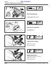
2. Replace end cap (#12) and flat washer (#11) on shaft
of mounting tube (#15).
3. Insert shaft of mounting tube (#15) fully into
bearing (#10). Turn bearing eccentric locking collar
clockwise and then tighten set screw in locking collar.
4. Reattach rear roller arm (#16) to seeder panel with
1" clevis pin (#9) and 3/16" cotter pin (#8). Be sure to
bend one leg of cotter pin to secure it in place.
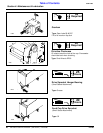
5. Insert stop pin (#7) in seeder bracket and secure with
hairpin cotter (#6).
6. Reattach scrapper bar (#5) to left and right rear roller
arms (#16) with 3/8"-16 x 1 1/4 GR5 hex head cap
screws (#4), flat washers (#3), lock washers (#2) and
hex nuts (#1).
7. Reattach packer chain (#6) or turnbuckle (#7) to rear
roller arm (#16) with remaining hardware.
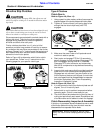
Rear Roller & Spacer Assembly (Left Side)
Figure 4-7
12872
26725