10
Section 1: Assembly & Set-up
OS1548 and OS1572 Overseeder (S/N 166724+) 308-303M
2-16/09
Land Pride
Table of Contents
Quick Change Rotor
Attach a chain, cable or lifting strap to the two
Overseeder sling brackets. Use an overhead hoist for the
rotor installation. Raise Overseeder.
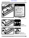
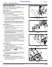
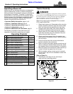
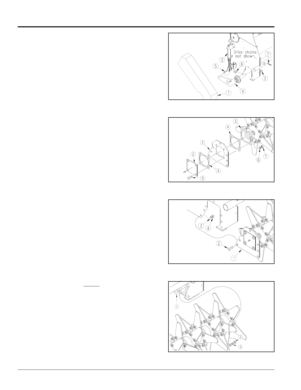
Refer to Figure 1-2:
Complete steps 1 to 4 if your Overseeder comes
equipped with a gauge wheel drive. Skip to step 5 if it
does not have gauge wheels.
1. Remove chain cover (#1) on the right hand side by
removing 1/4” x 1/2” long bolts (#2).
2. Disconnect right hand spring loaded gauge wheel
link (#3) from the right hand gauge wheel arm (#4) by
removing 5/8” x 2 1/2” long bolt (#5) and 5/8” nut (#6).
3. Remove drive wheel chain.
4. Remove cotter pin (#7) that retains the right hand
gauge wheel arm and remove gauge wheel arm
assembly. Be careful not to loose any components.
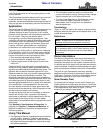
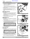
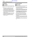
Refer to Figure 1-3:
5. Remove right hand bearing mount plate (#1) from
Overseeder main frame.
6. Separate right hand bearing cover (#2) from right
hand bearing mount plate (#1).
7. Between these two parts (#1 & #2) are two bearing
mount gaskets (#4). Place one of these bearing
mount gaskets between the bearing mount (#3) and
the bearing mount plate (#1).
8. Then place the other bearing mount gasket between
bearing mount plate (#1) and bearing cover (#2).
9. Retain these parts with 1/2” x 1 3/4” long bolts (#5),
1/2” lock washers (#6) and 1/2” hex nuts (#7). Hand
tighten nuts at this time. Final torquing of these bolts
will be later in the assembly process.
10. Check to make sure set screws in the hub inside the
bearing mount (#3) are loose so it is free to rotate on
the rotor shaft.
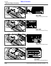
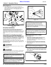
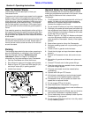
Refer to Figure 1-4:
11. Lift Overseeder high enough to roll rotor into position
under the Overseeder frame.
12. With rotor properly positioned, slowly lower
Overseeder making sure the right hand bearing
mount plate (#1) is to the outside of the right hand
frame end panel.
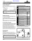
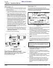
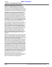
Refer to Figure 1-5:
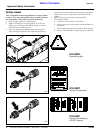
13. Connect rotor to rotor drive hub (#1) on the left hand
side using 7/16” x 1” long bolts (#3) and 7/16” lock
washer (#2). Leave bolts loose.
Refer to Figure 1-4:
14. Connect right hand bearing mount plate to the
Overseeder main frame using 1/2” x 1 1/4” bolt (#2),
1/2” lock washer (#3) and 1/2” hex nut (#4). Draw
nuts up snug, do not tighten.
Gauge Wheel Drive Disassembly
Figure 1-2
Bearing Mount Plate & Rotor Assembly (RH Side)
Figure 1-3
Rotor to Overseeder Assembly (RH Side)
Figure 1-4
Rotor to Overseeder Installation-Left Hand Side
Figure 1-5
14594
14592
14703
14645


